|
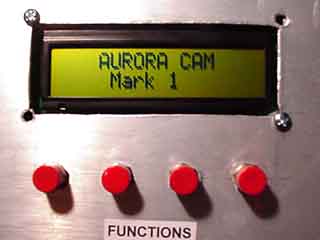
The
Aurora Cam
Mark
I
 |
The
Hardware Overview - I |
Uploaded 12/28/03
 Five images:
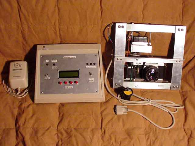 |
Left:
The main operating console, power supply, and robotic camera
frame. The frame plugs in on the rear, as does the 12v 1.5A power
supply. A test roll of PPF400 for scale... |
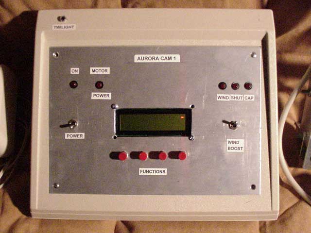 |
Close
up of the main console, belies its complex programming within.
Besides some power regulator lamps, a 16x2 LCD display for setting
up parameters and exposure status is included. Four function
buttons allow selecting settings in the LCD menu, such as exposure
time, and number of frames, delay between frames and activating
the twilight response. Note the twilight photocell at upper left. |
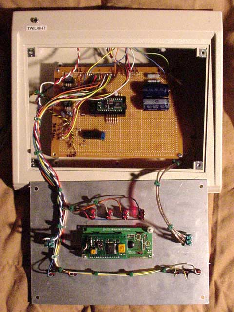 |
Under
the hood, The PCB contains two voltage regulators for electronics
and motors, the Parallax BS2 microcontroller, servo filter caps,
and at the bottom, the amplifiers for twilight and humidity sensors. |
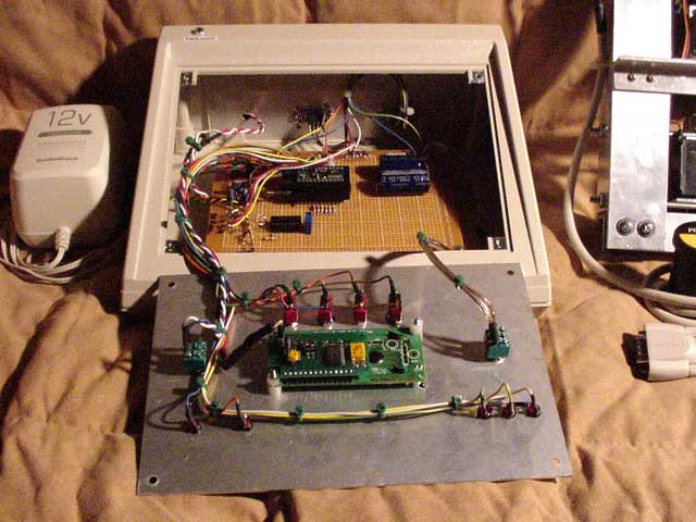 |
Under
the hood 2, showing the serial LCD display and wiring on the
front panel more clearly. |
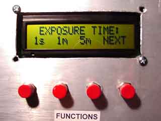 |
A
typical menu item such as exposure time can be set up by simply
selecting the appropriate button below or using settings from
last time to save time. The menus take up A LOT of processor
memory! I'm at the absolute limit on EEPROM. (2k) |
HOME SCHMIDT GALAXIES EMISSION NEBS REFLECTION NEBS COMETS GLOBULARS OPEN CLUST PLANETARIES LINKS
|
|