
Introduction to Concept
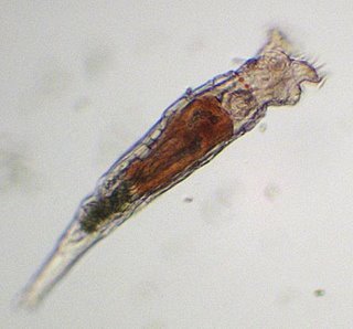
To demonstrate the two photosensitive eye spot animal level of intelligence, we have chosen the lowly microscopic yet multicellular fresh water animal known as a "Rotifer". These tiny swimming worm like creatures have amongst the smallest number of brain cells in the animal kingdom in their head region, with it still being considered as being its brain. Roughly 200 neurons control this animal, and with the addition of two photocell like non image forming eye spots, the vulnerable creature can navigate its environment seeking safety, food and avoiding obstacles to a limited extent. This makes it a perfect animal to emulate in our bio mimetic dual pixel vision project which we will be detailing here.
Left: A microscopic view of a Rotifer. The eye spots are on the upper right of this image, on the top and bottom of its head seen here as small black spots.
Advantages of Dual photo receptor vision.
Compared to the hapless Euglena, which is a one celled protist with a single eye, the Rotifer has the added advantage of being able to determine the direction of both light and dark areas by the relative intensities on both eyes. Since these eyes do not form images, they can only see shades of gray, and the rotifers tiny almost non existent brain can deal with this as a purely reflexive response to dark moving shadows such as a predator might produce just before munching this poor rotifer, or the ability to directly swim into the light where food will be at a maximum in the day time. Remember, with one eye, you cant determine direction without moving your entire body around in huge looping motions, but when you have two eye spots like our friend here, you have instant information to react to, this an evolutionary advantage.
Applications for small mobile robots
I will be demonstrating three possible uses for a two pixel gray scale vision system. When I say "gray scale" I am referring to the 10 bit (1024 shades) of Gray scale information available from each photocell. Unlike digital IR retro reflectors or proximity detectors which give only 1 or 0 output, the gray scale data allows us to be far more flexible in our behaviors and are a huge advantage in varying light conditions.
The Three Primary Experiments
Experiment 1 demonstrates how a robot can remain stationary and rotate its entire body to face the currently brightest light source in its field of view. To show this, I move a flashlight all around the robot, which then reacts by constantly pointing its front side toward the light source.
Experiment 2 demonstrates a more mobile behavior, in which the robot will move toward the light and follow it around endlessly.
Experiment 3 shows how we can use gray scale data to follow a black line on the floor to guide the robot to its destination.
Finally, Experiment 4 is to show a very powerful tool - Frame Differencing can be used. Here we present both a light object and black object to the stationary robot and it reacts only when movements into our out of the field of view occur.
Programming
As you might surmise, to keep in line with the simple brain of the Rotifer, our programs are very short, simple yet demonstrate what can appear to the average person a show of animal like intelligence, as far as the visual response goes. Indeed, that is our goal here, not to demonstrate the entire organisms complex behaviors, just the visual part where robotic applications are maximized.
For Experiment 1, the photocells voltage from an op amp buffer are read into the A/D converter of the robots 16F877A Processor, where they are digitized in 10 bit resolution. Three IF/THEN statements compare the right and left readings. First, if the absolute value of the difference between both readings is less than a threshold, the robot does not move and the light is considered centered. the pseudo code for this looks something like this:
IF ABS (CDS1 - CDS2) < N THEN NO_ROTATE
and the program jumps back to start of the loop. For differences larger than the threshold N, the robot either rotates to the right or left depending on which photo sensor has a higher reading. Using Grayscale data would also allow the robot to rotate faster if the difference is greater in a proportional way. A pseudo code might look like this for the main comparisons:
IF CDS1 > CDS2 THEN TURN_RIGHT
IF CDS1 < CDS2 THEN TURN_LEFT
This covers all cases and the robot responds by turning toward the brightest light.
The programming for Experiment 2 was similar, but instead of merely rotating, three commands were used. If the right side was brighter, the left wheel was driven, IF the left side was brighter, the right wheel is driven. And finally, if both photodetectors (Which are Panasonic 1801L visible light photo transistors) are similar within a defined tolerance, the robot drives forward. This is exactly what a Rotifer would do to move into the light.
For the Experiment 3, the robot is set on the line such that the photocells are on both sides reading the white background. This saved, or "memorized" shall we say in bio mimetic terms, and used for a reference. This way it DOESN'T MATTER WHAT THE AMBIENT LIGHTING IS. It will still be the background. Now if the readings on any photocell "eye" is less than half of the reference, then your over the black line. So if the right cell gets dim, you turn toward the right, if the left side gets dim, you bank left. The object is to keep the line between the cells. If both read the same as the background, then go straight. In programming terms, this is the pseudocode:
CELL VOLTAGE = CDS
IF CDSR < (REFERENCE/2) THEN GO_LEFT
IF CDSL > (REFERENCE/2) THEN GO_RIGHT
ELSE GO_FORWARD
In addition to this I added a condition that if the cells both read dark, to stop, and this way I can put a cross piece of tape on the line to act as a stopping point for the robot.
As you will see from the movies, the gray scale line following technique worked very well. I then turned most of the lights off in the room such that only a very dim lamp was barely lighting the arena. It still worked perfectly, since it took a floor reference at the start and used it to follow the line. The applications for robotics are quite numerous here. The use of an auto calibrating line follower can be used to deliver packages from room to room, work on factory floors or in the home follow a strict cleared path to accomplish a task such as watering the plants from room to room.
For the final Experiment 4, we employ frame differencing by taking readings on both cells, storing them and half a second later take the readings again, and subtract them from the first readings. Then we compare, react and repeat over and over. What this seemingly mindless activity does is identifies when the field of view changes in brightness either up or down from a half a second ago. This is exactly how insects see the world, and many small animals use the method as well to spot small moving prey. The programing is straightforward:
IF ABS (CDS_OLDRT - CDSRT_NEW) > N THEN SAY_LEFT
IF ABS (CDSLT_OLD - CDSLT_NEW) > N THEN SAY_RIGHT
Where N is a small number used as a detection threshold, and the readings for the RT side and LT sides are taken in pairs 500mS apart before comparison.
Movies
Four movies in mpeg format are provided, which will play in the Windows Media Player when clicked. Turn your volume up since the robot is talking at a fairly low level...
Conclusion
Unlike many home robots with two IR prox sensors used to avoid obstacles, having a 10 bit gray scale two pixel vision array has many more advantages and is far more flexible in applications. And without a doubt, such analog style vision with simple behavioral programming can easily emulate the visual intelligence of the Rotifer, a small microscopic wonder which leads its entire short life interacting with its tiny world on two photosensitive patches on its head.
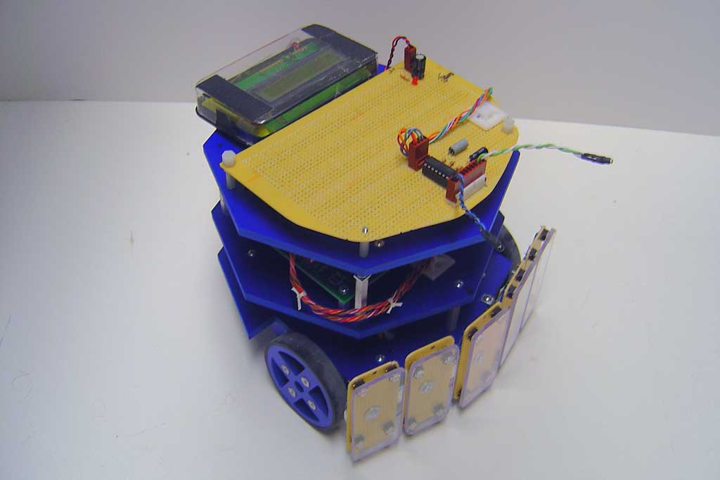
Still Image 1: Overall view of the Rotifer Robot. The two photo transistor "eyes" are on three inch stalks coming out of the front of the top of the robot. The circuit board on top is the op amps used to interface with the analog inputs of the 877a chip below.
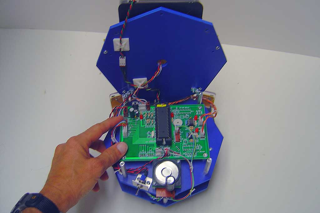
Still Image 2: Under the hood. With the lid on a hinge, I can easily access and program the processor (center) mounted on a ZIF socket for easy programming. the large silver disk at the bottom is the speech processor SP03.
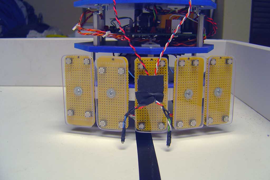
Still Image 3: Front view when configured for Experiment 3, line following. the cells are on longer twisted pairs, and mounted to the front bumper so they look on both sides of the black tape line to follow.
Movie 1 Rotation toward the light source.
Movie 2 Follow the light source.
Movie 3 Follow the black tape line to stop. Listen to the robot say its starting and ending when it finds the black cross line.
Movie 4 Frame Differencing demonstration. Listen to the robot say "Right side" or "Left side".