|
|
|
|
|
|

Click on Thumbnails for large view
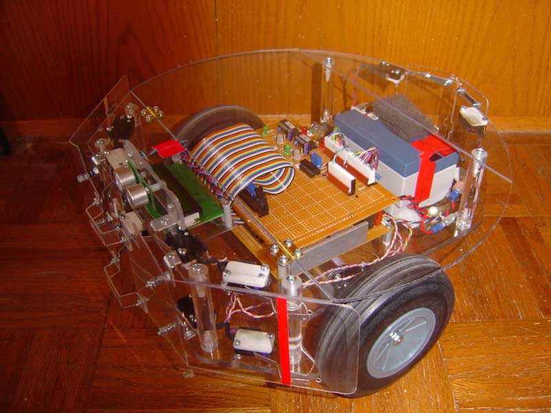
Here we describe the stasis sensor and encoder used in our latest robot, PAAMI. Every robot encounters a situation in which it may be stuck, and the sensors do not detect the condition. When this happens, a robot will continue to spin its wheels, thinking its moving forward, with no impacts from either the bumpers or any IR sensors. Unless something is done, the robot will simply run down its batteries and stop functioning after a while. An example of this condition, is when a robot gets hung up on a rock, or piece of furniture and flails back and forth trapped. Since no forward motion is occurring, the addition of a Stasis Sensor will enable the robot to detect its stuck or trapped condition, and take actions to escape accordingly. Here is how our stasis sensor works, and perhaps you can modify it for your own uses.
Theory of Operation
Most robots use two drive wheels mounted centrally, each independently driven to achieve forward movement and turning rotations. At a point exactly in between them lies an interesting point. This is the ONLY location where a robot can get stuck, with wheels skidding or rocking back and forth trapped and a detection be made with some confidence. A freely rolling wheel is placed in this location, with an encoder disk secured to its side face. An optical detector such as a photo interrupter or reflective sensor looks at this sensor, and sends the data to the processor for analysis. When the robot is moving, the wheel is turning and the processor counts the pulses per interval of time, say for 5 seconds. Normally, the counts will exceed a set value, say 10 counts per 5 seconds or more. When the count is lower, anywhere from 0 to 9, the robot is either stuck, slipping or simply not moving. Thats the theory behind the Stasis Sensor.
Implementation
We first made a wheel out of lexan sheet stock on a lathe and put a nice v groove in its edge. A rubber O ring fits in the groove and acts like a dandy non slip wheel. we next drew up the encoder pattern in Autocad, and printed it out full size. Attaching it to the side of the wheel was easy, we used a glue stick. The wheel was mounted on an axle and two arms that are hinged to the bottom of the body. This way the wheel rides on the surface between the drive wheels and can move up and down on an irregular surface. The optical reflective encoder is a Fairchild QRB1114 sensor, available from Digikey. Since our bot has priority arbitration architecture, we elected to use a PIC12629 microcontroller which cost less than a buck for the stasis sensor controller. The controller has one function in life - count pulses for 5 seconds, and if its less than 2, then the output line goes high. Thats it. I do also have a 10 second delay before the program starts in the PIC to allow the robot to power up and get going.
Caveats
So what level of priority to we put the Stasis sensor? It cant be at the top, or we would never be able to stop the bot for sleep, or picking up a toy. It must be subsumealbe by other more important levels. We tried it in the lowest module, and that didnt work either, since everytime a higher level stopped to avoid an impact, and then returned control to the lower levels it would always jump into an stasis escape mode. What we finally deceided upon was to treat it like an IR impact, and put it at that level, about half way up the priorities.
You must be careful not to allow the Stasis sensor to control the bot when it tries to sleep as well ! So careful placement in the control hierarchy will give great benefits, and make your robot a true escape artist.
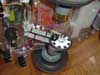
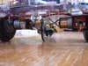
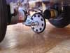
With the robot tilted on its side, you can see the wheel, and armature assembly that keeps the wheel alway on the ground. Ground view from the front showing the stasis wheel riding well exactly between the two drive wheels. It must be large enough to clear the obstacles it is expected to see. ( like socks, cat toys, and yes, the drive through the moist cat food dish) Rear underside view of wheel touching floor doing its job. Note the Fairchild sensor also rides up and down with its wiring with the wheel. MPG Movie (441k) Be patient with my attempt to make the robot think its slipping. I grab it by the rear, and the wheels are slipping away. At some point, the stasis sensor kicks in, and it goes into a peculiar escape maneuver - rocks back and forth in reverse in an attempt to free it self from the offending obstacle. Then it rotates a random angle, and goes onward.