
|
|
|
 PicBot III
IR Proximity Development Robot
PicBot III
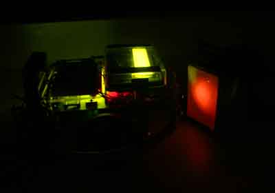
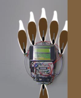
IR Proximity Development Robot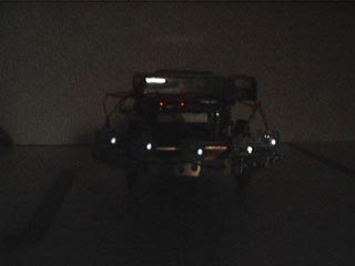 PicBot III imaged with IR enhanced
web cam at night showing IR sources
PicBot III imaged with IR enhanced
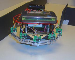
web cam at night showing IR sources| PicBot III was developed specifically for this project. To simulate the perfect household robot shape - a circular disk, the square PicBot was modified by adding an aluminum ring, 7 inches in diameter suspended at a nominal height of about an inch off the floor. Aluminum clamps were mounted on the ring, where we installed the IR Prox sensors on posts. These could be rotated to any angle for evaluation. |
|
Introduction In this report, we are now concerned with the second most common sensor that home roboticists install on their robots, Infrared Proximity Sensors. In our previous report on "Bumper Logic", we discussed in great detail the reflexive behaviors and time/event related behaviors that a robot must make to successfully navigate in a household environment. Please read Bumper Logic first, if you have not already done so as you will get a clearer understanding of the differences. Here, we are using a very similar approach, in that the IR Prox sensors as they are commonly refereed to are merely virtual extensions of the physical bumpers themselves, but with some very peculiar oddities to consider. We will cover the similarities and differences of each system. It is a required prerequisite that you read the Bumper Logic article to fully appreciate the Prox Sensor design concepts. Proximity sensors purpose For a household robot to successfully navigate to its destination in the home environment, perhaps on its way to the kitchen to sweep the floors at a specified time, a method of both avoiding unplanned obstacles, and determining the location of walls or barriers is essential. While bumper navigation requires the robot to impact - in essence feel its way around, a more sophisticated method is called a "non contact bumper" system. Typically, such a system consists of several infrared beams projected onto the direction of the robots travel, and sensors look forward for any reflections which indicate a nearby reflective object. It is very important here that you understand one main limitation of such systems, in that they provide only a single bit of detect/non detect and do not provide any distance indication. This is because the reflectance of the obstacle is never known for certain in a household environment. IR ranging type sensors will be covered in a future report that can provide this type of information. |
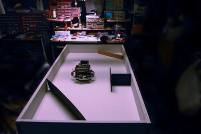 |
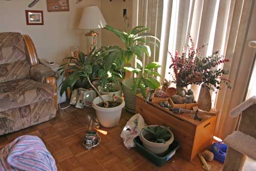
PicBot III Test Arena Here in our lab, we are able to provide under controlled conditions various surfaces, entrapment situations, and rigorous testing of the robots Finite State Machine program architecture. Later, after development in the arena, the robot was allowed to roam free in a household environment to fine hone the software and hardware development. |
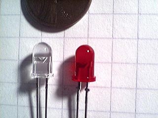 |
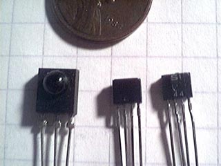
Reviewing infrared sources Let's start our discussions with the source of the beam of light we project forward from our robot to search for nearby obstacles. The basic concept seems simple enough: Project a beam of light forward and look for the reflected light returning to detect an object ahead. In essence, it is considerably more complex than this, so lets start with the basics. Here we see two LED's. The one on the right is an ordinary high output red LED, which projects a fairly broad beam of about 90 degrees in front of it. The red LED is not only slightly diffuse - translucent is the industry term, but it is also long and is capped with a rounded lens surface. Now look at the LED on the left. This is a infrared LED, with a water clear enclosure and a bit shorter length. This type of source projects a much narrower beam, |
|
about 45 degrees beam width and it is much sharper edged and focused. IR LED's come in two flavors which you must be cognizant of when selecting one for your application. The commonly used type for IR security systems and most commercial applications are 880 nanometers wavelength. They are bright, inexpensive and usually labeled as simply "IR LED's" in catalogs. The other type is 940nm wavelength and is used for IR proximity, ranging and measurement systems. The wavelength here is the key, it is farther into the infrared and thus more easily separated from standard room or sunlight with wavelength specific sensors. It is these we are interested in most for our robotics applications. IR LED's also have several other unique characteristics we find desirable. First, they are inexpensive running about 50 cents each. Second, they are modulateable at frequencies both low and well into the GHz range. This will enable us to further isolate their light in well lit rooms. Next, they adapt very readily to use with microcontrollers. Our PIC processors can drive several LED's directly with their outputs. They are also small, and come in several different sizes. Finally we can vary their brightness with either current limiting or with pulse width modulation (PWM). All in all, a very handy device! |
 |
Reviewing common sensors Left: Here we see two different types of the most commonly used IR sensors geared toward robotics applications. On the far left is the Panasonic PNA4602 sensor and on the right front and rear views of the Sharp IS471F sensor. These are in normal room lighting. Right: The same sensors photographed in infrared light showing the now transparent cases with internal details clearly visible. | 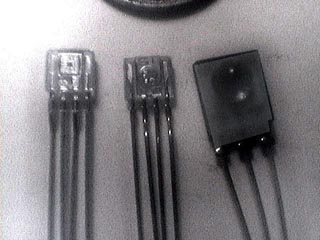 |
| Note that the PNA4602 is more translucent giving it a wider viewing angle. You can clearly see the die for the sensor embedded on top of another micro circuit for the rest of the internal functions in the leftmost IS471F sensor. These IR sensors are inexpensive, in the 2 - 3 dollar price range each, and are designed to receive modulated IR and put out a digital TTL level detect signal which can interface with your microcontroller directly. The IS471F in particular is very handy, it not only receives modulated IR, but GENERATES a modulated waveform as well and can drive two high power IR LED's with no additional IC's. This is why we have selected this superb device for our robots. |
|
Mechanical/Electronic Architecture At this point in our discussion, we need to address the physical mounting issues, electrical design and optical implementation. As illustrated earlier, there are two possible configurations that are popular today. First, is the PNA4602 approach, used by many robotics designs like the Boe Bot from Parallax. Its strengths are great sensitivity, and a built in Automatic Gain Control (AGC) that turns up the sensitivity in dim lighting to a substantial degree. To use this highly popular part requires you to first build a driver circuit for the IR LED which generates square waves at a rate of exactly 38.5 KHz. An internal band pass filter detects this frequency, and isolates it from the bright visible light and the internal detector will put out a TTL level 1 for no detection, and 0 for detect. However, as commonly used as this component is, it has several major drawbacks. First, you must construct some sort of 555 or nand gate logic oscillator, at 38.5KHz. That will take up significant board space, but with a set of driver transistors, you can drive all of your LED's. But the AGC is the real issue. In a dark room, when the gain is at a maximum, the detection range for a white wall is several feet up to a yard. Can you imagine your robot navigating around with a virtual diameter of six feet? In bright room light this detection range is around six inches to a foot. We felt that this part did not allow proper navigation in darker rooms and such and was passed over for a far more modern device that surpasses it in nearly every way. A superior component arrives on the scene. Lets discuss the IS471F from Sharp. This device, which Sharp calls "An OPIC Light Detector with built in signal processing and internal light modulation system". What this means is it is a very sophisticated part. First, it is 1/4 the size of the PNA4602. When supplied with 4.5 to 16volts DC, it actually generates a perfectly matched 8 KHz square wave which then can be used to directly drive two high power IR LEDs in parallel with no external resistor right from the device output pin! Also, the case is molded out of a visible light blocking epoxy, so it appears black in visible light, but transparent in IR, (See photo above) which allows it great discrimination even in bright sunlight. Further, the part does not gain up so much in the dark and the detection range stays very constant under nearly any lighting situation. In summary, it is the perfect part for us robotics engineers to use for an IR Proximity detection system. |
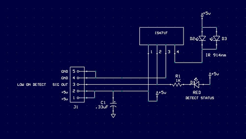 | The schematic diagram for our IS471F PCB. The only external components I've used besides the two IR source LED's are one surface mount red LED indication lamp for prox status, and its associated current limiting resistor. Also, a .33 uF cap was installed to keep the switching transients from getting back into the 5v line. |
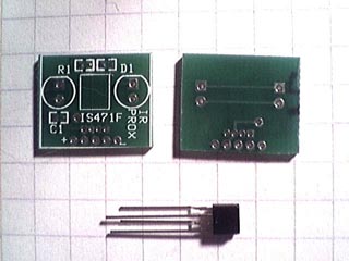 | For repeatability in these tests, the author designed circuit boards for the IS417 sensors, which allowed the installation of one or two 940nm LED's to use in small or larger robots. A large panel of a matrix of boards was made by ExpressPCB, and cut apart for assembly. On the right the boards were mounted by gluing a post on the back, and the bumper ring has a clamp to hold the post so I can rotate the sensor to different angles for evaluation on different beam patterns. | 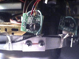 |
|
Mechanical Mounting Considerations For PicBot III, the small boards were mounted on wooden dowels so they could be rotated for angular testing of various orientations. For a more permanent mounting, the boards can either peer through a slot in the body of the robot, or be mounted inside small plastic boxes with the top left off to let the beams out. This is what we did with PAAMI. You still may want to be able to rotate the boards or hand wired perf board that contains your circuit (PAAMI was hand wired) to experiment with different angles. One thing you will HAVE to do is put some black shrink sleeving over most of the barrel of the LED. This is to prevent side spray from activating the sensor. 1/4 inch heat shrink or black tape works just fine. |
 |
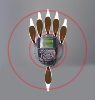
Viewing the IR beam pattern with the IR Phosphor In total darkness, a Kodak IR phosphor card was used to directly convert the IR light at 940nm to an orange visible light for viewing of the beam directly. These cards, available at Edmund Scientific allow the engineer to directly measure beam spread and brightness gradations of the IR LED source. This is a 15 second exposure at ISO 800 with a Canon 10D DSLR. |
|
Visible Light and Infrared Light Comparison Below are two images taken consecutively. The image on the left is a standard camera shot, in what we would call the visible spectrum. On the right is the world our robots see - the world of deep infrared. This shot was taken with a special IR filter which excludes all visible light. Now lets take a closer look at the photos and see what the robot will see in detail. (You can see PicBot III next to the big pot) |
 |  |
| Wood items, that are not varnished appear as pure white in IR. On the left, look at the wall hangings made from bark and wood. Both appear pure white in IR. The plants are really interesting, they are of course medium green in visible, but in IR the appear bone white! The flower pots are another case in point. In white light, both large flower pots appear white. But look at what happens to the one sitting in the green tub in IR. It appears dark now. The lesson here is that plastics can appear any shade in IR no matter what they look like in visible light. Finally - and this is really important, the pattern of sunlight on the floor is very different in IR. See the stripes on the floor in IR, not seen in visible. This can trick a robot into seeing a reflected beam, so that is why we modulate our IR . |
|
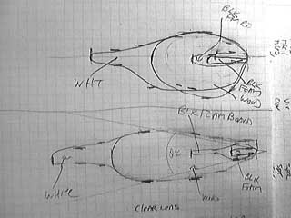
Measuring Beam Spread Patterns For accurate placement geometry and coverage for a robot, we must next determine the shape of the detection pattern of our sensor/receiver combination. To do this, the sensor is clamped above a sheet of graph paper at a distance it won't detect the papers surface. (about two inches). Next, we select several materials to insert into the beam to measure the maximum distance we can detect that color and texture. IR prox sensors activate when a minimum threshold of light reflected back to the receiver has been crossed. This range is not constant, for white objects it can be up to a foot, but for black surfaces it will be only an inch or two, or maybe not at all for really dark non reflective materials such as black felt. Since our robot will never know what the reflectivity is of an obstacle - whether it is a white wall or dark sofa, we must determine the characteristics with a range of materials. |
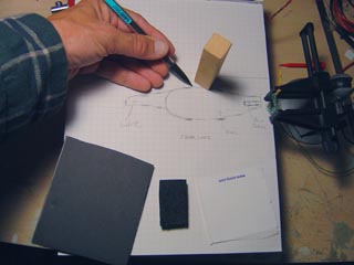 | The technique is simple, move the obstacle into the beam and when its output goes low (active low) a standard red LED will light and indicate the IR reflected threshold has been crossed. Here I am using four materials: A pure white Avery label paper, a block of wood similar to furniture legs, black poster board, and the darkest and hardest to detect - black IC foam. We use the pencil to mark the various points that the surface is first detected for all the chosen materials that will represent the expected range of reflectivities found in the home environment. The results were somewhat surprising. The choice of LED determines primarily the beam detect pattern. While the IS471F can receive a very wide angle of nearly 180 degrees, the narrow beam clear IR LED really determines the detection lobe. |
 |
Left: Detection lobe tracings for a diffused LED on the top, and the preferred narrower angle water clear LED on the bottom for the four materials. Right: Next we scan the drawing with our flatbed scanner, import into Photoshop and fill in the lobes by painting them in with the four colors of the test | 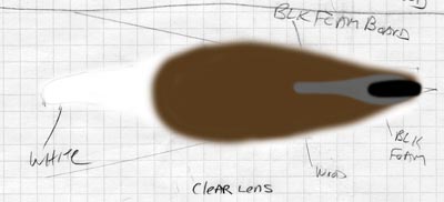 |
|
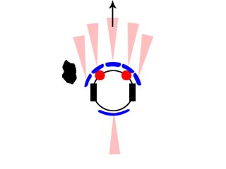
materials. We will use this graphic later on to apply to aid our design of the actual robot sensor array. Defining the number of sensors As with the bumpers we examined with PicBot II, extensive testing revealed that the same five front/one rear pattern was both sufficient and had excellent coverage. Also, we can modify our hard earned bumper logic program for the IR if we realize that IR Prox sensors are merely virtual extensions of the true bumpers on a robot. Also by keeping the number the same, we can actually put the IR sensor right on each bumper plate as an integrated unit. The robot can be quite modular in this respect, each bumper plate is an integrated fusion of both touch sensing and proximity detection. |
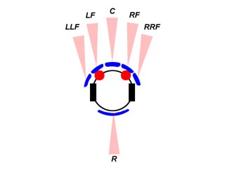 |
Defining the IR Prox Array pattern Here we maintain the terminology from the Bumper Logic program, of five frontal sensors, and one rear. The angles of the beams at this stage is unimportant we will discuss that in a bit. The length of the IR detection lobes seen here is similar to that of a white wall or surface and is at a maximum. The lobes will be much shorter for dark objects! |
|
Beam Spread Patterns discussion The angle at which the five detection lobes extend outward from the front of the robot will depend on many issues. Considerations include the size of the robot, beam spread patterns, and most importantly - the application. For a home environment, your robot will either stay away from everything as far as possible, or work its way into smaller areas and narrower hallways. For example, a robot that is designed to deliver laundry from one room to the next should not enter small confined spaces and try to keep away from nearby obstacles as much as possible. On the other hand, a vacuum robot must get into small tight spaces to effectively clean the most areas. Here we will discuss the pros and cons of each type of spread pattern and then you can select the spread that most suits your application. |
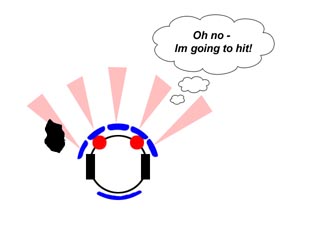 |
Broad beam spread pattern Here, PicBot has a wide detection lobe spread of around 120 degrees. The virtual size of the robot is huge, and even coming near a obstacle that it will not come close to hitting will trigger an escape response as seen here. If you have plenty of large rooms with big door openings, this will work fine. But the robot will spend a lot of time "escaping" obstacles that are really of no danger. |
 |
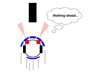
Narrower Beam Spread pattern Another approach is to point the beams almost directly forward. Now we are treating the detection lobes as "bumper extensions" and when an object is seen by the prox sensor, it is truly a danger to avoid straight ahead, just like the real bumpers reaction would be. Here, PicBot passes by the obstacle, only concerned with objects that just come near enough to almost skim the sides. Such a configuration allows the robot to traverse narrow passages more easily but can run into a very black barely reflective object on the side. Thats where the real bumpers take over! |
 |
Less than ideal beam pattern A very common configuration for many budding robot builders is the dual beam array seen here. In no time at all, the robot will find itself trapped in a home environment, unless its very plain and rather empty of furniture. This type of arrangement is fine if you have the bumper as a backup. It will certainly be banging around the home not seeing objects directly in its path. We don't recommend this type of arrangement, however a central beam would help a lot here. |
|
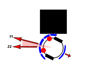
Behavioral Programming and Artificial Intelligence We discussed in great detail in Bumper Logic the standard reaction each bumper plate will initiate when an obstacle is detected. And because we kept the number and configuration for sensors on our IR the same as the Bumpers, the same logic follows for reacting to an impact, with a few interesting exceptions. This will be a huge time savings in writing code, since much of the reactions to a virtual extended optical bumper are exactly the same as a physical bumper. Now lets get into some detail on the similarities and differences. Ballistic/Reflexive Responses: Central Frontal Impact
Right and Left of Center Impact
Far Right and Far Left of Center Impact
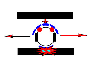
Rear impact
|
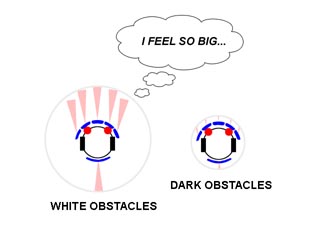 |
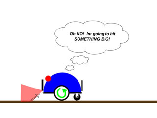
The Virtual Size of the Robot Proximity sensors have one major drawback you must be aware of. Because the detection range is proportional to the reflectivity of the object in IR, you can never know how far an unknown obstacle is from the robot. You can only know there is something near. For a white object or light colored walls, the detection range can be six inches to over a foot with a simple one LED source. In a dark room the PNA4602 turns up its gain and you will see objects several feet away. But Thats for objects of high IR reflectivity. But if its dark cloth, shoes, or even a baseboard, that range can be only inches. So your robot has a virtual size that depends on the reflectivity of its surroundings. In a white room, the robot can be three feet in diameter! But in the confines of a dark couch, or near a black bedspread the robot shrinks to barely an inch over its physical size. That is why it is difficult for precise IR prox navigation in a home environment, you never know what the virtual size of your robot is at any time. |
 |
Defining the robots virtual envelopes Detection Lobe patterns we measured earlier are now superimposed on the image of the actual robot. All four brightness targets are represented here. You can see now that for the white surfaces, the robot is easily 3 times larger effectively for moving about the home. But look how small it is for black obstacles. You will barely detect them before you hit them. There is little we can do about the reflectances of household obstacles, but if we are aware of this concept, we can more effectively deal with it mechanically and with our software programming. |
 |
Room Shrinkage Here we demonstrate how the room size seems to shrink using IR prox sensors for our impact avoidance system. The lower robot has only bumper impact sensors and can travel over a much larger area in the room without reacting to an obstacle. The upper robot has IR prox sensors and must turn away from the walls and obstacles much sooner, since the virtual size of the robot is actually 3x larger. The behavior of the robot can be much different even with the same escape algorithm in the two robots. |
 |
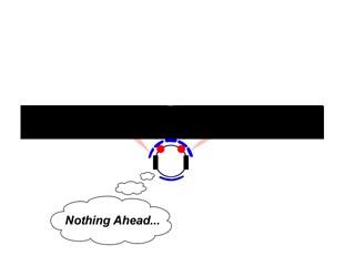
Ground Spray issues When selecting both beam width of your array and the distance above the ground that it will be mounted on the robot, consider that the robot may see the flat ground in front of it reflecting back as an obstacle. This is major problem with sonar based navigation especially outdoors with the small pebbles on the ground. In the household, a rough carpet, small ledge or trim of no consequence may fool the robots IR prox sensor into seeing a reflection ahead. The robot may react rather oddly trying to escape the phantom obstacle. By knowing your beam detect lobe pattern in advance, you can be certain of taking control of this problem and looking ahead with a narrower beam and not detecting the ground. |
 |
Encountering a non reflective surface The laws of physics tells us that if the reflective surface is black enough, then the obstacle will not be seen. In a household environment, there will always be something that is too dark, such as a dark sofa, black shoes, or maybe that pair of dark socks left on the floor. Since we do not wish to increase the power level of the IR LED light source to keep the virtual size of the robot from growing too large, we must resign to the fact that the backup bumper system will have to take over if such an encounter occurs. We cannot stress too much that IR Prox sensor navigation can be considered reliable only if backed up with a contact type sensory array as well. |
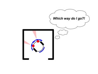 |
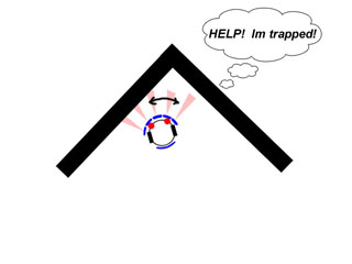
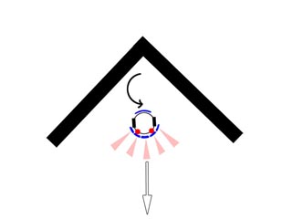
Small Room Entrapment Unlike bumper navigation arrays, IR Prox sensors will render the robots virtual size up to three times larger as far as obstacles are concerned. A very common entrapment you will encounter will be the robot getting trapped in a small confined area. Because the the limited resolution of the array may allow all to often the robot to enter a small area, it may find it self unable to find an exit since every direction seems to be an obstacle or wall. There are two ways out of this entrapment. First, the robot can look at all its sensors and see if there is one that is not detecting an obstacle, then turn that way to hopefully find the way out that it came in. Second, failing this, if repeated attempts do not yield a timely escape, the robot can choose to ignore the IR Prox sensors and escape with bumpers only. This usually works because the virtual size of the robot becomes the physical dimensions of the robot. Using both sensor types to escape in this situation is called sensor fusion, and having that bumper backup is a clear advantage in a home environment. |
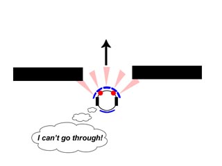 |
Narrow corridor/Entryway Entrapment Using wider beam spray pattern can result in the robots inability to enter passages and connecting hallways in the home environment. Since the robot does not know the reflectivity of the opening in front of it, it may have almost no clearance or a foot on each side. We could however do something that was impossible with bumpers, look ahead with the other available sensor lobes for a clear passageway. However there is a danger in doing this, white walls from the other direction may prevent us from returning thought the same opening. |
 |
Avoiding Narrow Corridor Entrapment One advantage to keeping the beam lobes pointing more or less straight ahead is that the robot will be able to enter and escape from narrow corridors in a similar fashion that bumpers can be used for tunnel escapes. Here, PicBot is traversing a corridor that is scarcely wider than the robot itself. |
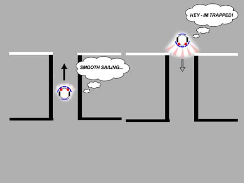 |
In this example, the robot on the left enters a hallway or passage to another area at the top. Walls or sides of the tunnel are dark, and the robot does not see them unless it nearly hits them. On the right, the robot will now attempt to leave the room, but the walls on this side are white or much lighter in IR reflectivity. The robot can now become trapped because it does not see a way to enter the hallway. This is the dark corridor entrapment problem. |
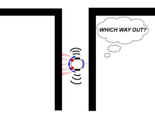 |
Narrow Corridor Entrapment (Tunneling) Like tunnel entrapment with bumper based navigation, the robot can become trapped in a narrow corridor which will cause all sensors to be active at once. The escape method here is first to try a random 90 degree turn. If that does not work, the approach we used with tunnel escape with bumpers will have to be tried, wall following. |
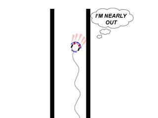 |
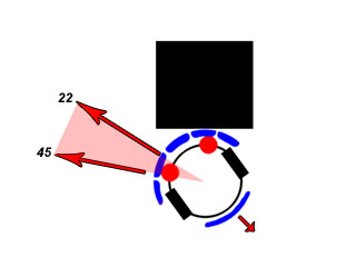
Escape from Corridor/Tunnel Entrapment Wall following with Prox sensors is a rather digital affair. This "Bang - Bang" approach is typical of either bumper switches or a threshold detect prox sensors. We can in this case however keep a fairly safe distance from the wall while escaping since the prox sensors do not have to touch the wall to detect it. As in small room entrapment, we can use sensor fusion to improve our chances of escape here as well. This is a great example of AI (Artificial Intelligence) If the IR Prox sensors do not extricate the robot in a timely manner from tunnel entrapment, the robot can try to ignore its IR sensors and escape with its bumpers, which have a much smaller virtual robot size, and is much better at this type of escape. |
 |
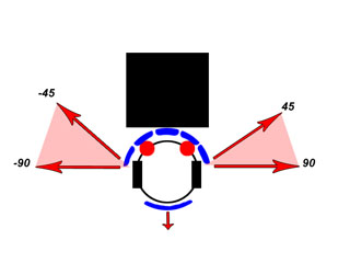
Wall following - Setting up the IR Prox Array It is critical to set up the outer prox sensors to be able to make an effective wall follow escape. Remember our nice graphical tracing of the detector lobe patterns we made previously? Now we will use that information. Here I have overlaid the beam patterns - or to be more precise, the detector envelopes onto a photo of PicBot III. We set the angle of the outer lobes to reach a wall when the robot is traveling parallel to the wall at a reasonable clearance, like half to one inch. But we cant use the black surface beam, its too small and we could not follow a white wall very well if we did since its beam reaches out so much further. I used the brown lobe, for the wood block. Most of the surfaces our robot will encounter will be wood, or medium toned in color. So we choose this for our wall setting. Set the robot next to the wall and adjust the beam so it just goes off. You can also do it graphically like we did here. The next beam in will cut this angle in two and split the difference. And obviously the center beam will point straight forward. |
 |
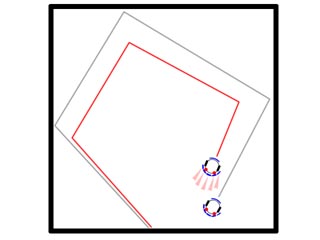
Canyon Entrapment It is actually far easier to become trapped in a corner with IR Prox sensors. The distance to the wall can be anywhere from point contact to up to a foot away for white walls. Exactly like we determined our canyon entrapment with the bumper logic, we can count either the duration between impacts or record the "R - L - R - L" pattern to activate the canyon escape behavior. |
|
Escape from Canyon Entrapment The best escape from canyon entrapment will be to do a 180 degree turn. We have found that for most cases, this will get the robot out of trouble. I made a movie of PicBot III performing such an escape. Check it out! |
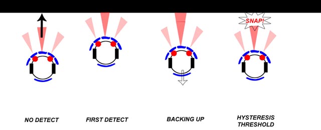 |
IR Prox Hysteresis You will notice an interesting phenomenon with the commercially available digital prox sensors. The first detect distance is less than the last detect distance by several inches. This is called "Hysteresis" and is added in by the manufacturer to prevent the sensor from oscillating at the threshold point from on to off rapidly. Be aware that your robot may have to back up a considerable distance, of several inches before it can free itself of an obstacle it encounters. This is one huge difference from bumper navigation, so please take note. |
 |
IR Prox Finite State Machine (FSM) I am providing you with our Finite State diagram to help you design the software for your IR Proximity array. Here we assume that if the array does not detect a black obstacle, that the bumper will and react accordingly. There has been many iterations of this basic design, and you may find that modifying it for your application will improve performance. I give this to you here to act as a starting point, one that works very well indeed. |
|
Conclusion We have seen from our experiments under both tightly controlled conditions in the robot arena and supplemented by home environment analysis that IR Proximity detectors can be a great asset for navigation and obstacle avoidance in the home robot. By knowing both the strengths and limitations of these sensors, and by providing you with an in depth knowledge of prox sensor design here, our goal to both improve the AI in our robots as well help you design your robot more effectively has now been addressed. Contacting the Author You can reach us at comets133@yahoo.comnospam (remove nospam from address) |