Project Overview
The original purpose of this project was to design an outdoor robot capable of movement and navigation through rough rocky terrain to a predetermined collecting area, obtain rock and soil samples from that area, then return them safely to the point of origin. This task has now been completed, with only a few compromises that are detailed below. This type of terrain as we have found is very hard on equipment, and demanding on drive systems. Each of the robots subsystems will be discussed below, along with an evaluation of performance of that subsystem and what may be done in the future for improvements. Here is the movie we made for this report of the Geobot in action at the site of geologic interest.
Lets start with the Robot base itself.
Tank Tread Drive system:
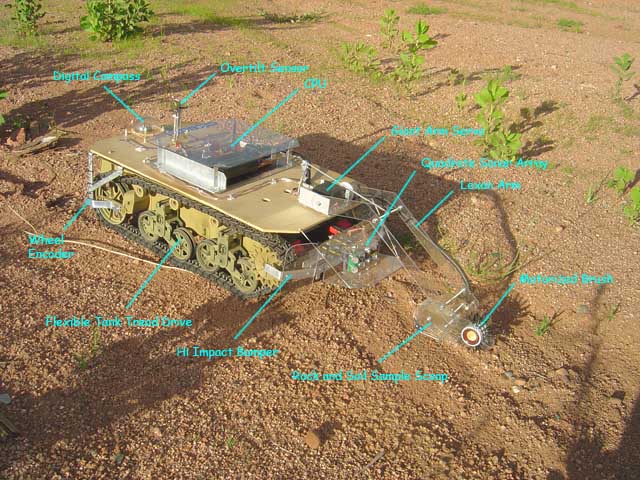
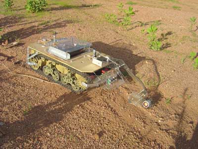
The robots base is the bottom half of a large radio controlled Stuart M5 tank base, purchased locally at a large chain department store. The original tank was huge, and had what appeared to be a well designed link type drive system, and came apart to the drive section easily with standard screws and bolts. The base also came with a generous 12vdc lead acid gel cell battery, and large automatic charger. The base performance has been variable at best. For straight runs, the base does well, overcoming nearly any obstacle in its path. It is when we tried turning the base with PWM or short drive bursts on each side that the problems multiplied. The amount of current the motors drew on the battery became huge, and occasionally a marble sized pebble could become lodged in the tread when rotating in place, and throw the tread off - or more often snap the tread into pieces.
For most of the testing, we avoided gravel surfaces and kept to grass covered surfaces, and smooth dirt with larger rocks, and we were just fine. The huge power draw of this base made runs of about 15 to 20 minutes as the upper limit before exhausting the battery. Fortunately, most missions were 100 feet or less and this was not a major problem.
Tank Tread Odometry:
A modulated IR wheel odometer was put on the back tread wheel for distance measurements. In an outdoor environment with a tank tread, there is really no hope of using differential odometry to move the tank in any precise manner. There is simply too much slippage on the ground, and in short order the calculations are off considerably. However we were able to very successfully use the linear odometry to measure the total distance traveled by measuring the encoder counts for the straight parts of a long run. This usually got us within 10 percent or better of the correct distance to the collection area. Ideally, a GPS based system may have worked better for long distances, but for the short missions of less than 100 feet, a beacon to home in on would be the best solution, be it active or passive.
Bumper Array:
This plunger type system worked rather well, taking heavy impacts with such a heavy robot base into large rocks without any major problems. A standard bumper connected directly to the lever switches would not have lasted long outdoors. We knew that the sonar array would not catch all obstacles, especially obstacles low to the ground, or thin and narrow objects such as small trees. The bumper was able to alert the robot of any impacts, even low scraping hits with little difficultly. This of course should always be considered the last line of defense on navigation of the outdoor environment.
Quadrate Sonar Array:
This was the shining star of the Geobot’s navigation system. It is very challenging to detect low lying angled, or rounded rocks with a sonar system because of the reflections from the pebbles on the ground itself. By directing the sonar with a lexan deflector, we were able to successfully shape the beams to ignore most of the low, easily driven over rocks, and yet still catch a majority of the tall limbs, bushes, rocks, and sticks out to four feet or more from the robot, which allowed it to take proportional evasive maneuvers and make curving moves with the dual PWM drive to snake its way along the rugged terrain. The mapped array navigation worked very well, and will be used for future robots. A narrower beam array may have been more of an advantage here, and several new units have come out recently on the market which may have to be tried for future systems.
Devantech Digital Compass:
This is what enabled the robot to pursue a coarse to a distant target. It was very challenging to get the compass calibrated. It simply would not behave like the instructions dictated when we tried to bring it in for our latitude. After many weeks of getting nowhere, we found there was a discontinued model calibration method. Apparently we got some old software in our new unit and were able to get it to calibrate using the old method. It was quite a sight to watch the Geobot navigate amongst the large rocks, continually turning back again and again to the compass bearing after avoiding the obstacles. We made several movies of this technique to demonstrate it snaking amongst the rocks using its variable PWM on the tank tread drive, and then veer back to the original compass bearing and continue on to its destination. Will we use the Devantech compass again? Maybe.
Over-tilt Sensor:
I put this sensor on early on in anticipation of keeping the robot from not climbing too steep of a hill, or going down a steep embankment. The sensor worked by hanging a weight from a damped potentiometer. It actually worked well, and when on slick grassy slopes, it actually stopped the robot on a steep up hill climb and caused the robot to tack up the hill at a more gradual angle. This can be seen in this movie here, on an early test of the navigation system. The downhill was another matter. We found that if the robot is going down a too steep of an incline, it was too late to back up. The robot would slip its tread and go no where. So we decided to make the robot cut its speed down to at least make its essentially a free fall down the hill less severe if it impacted on a rock or tree. This actually worked rather well on the grassy slopes as well, since if it had to stop, it could do so without continuing to slide downhill.
Processor board:
The use of a 16F877a PIC Processor made running the large priority based Finite State Machines fairly straightforward, with plenty of inputs both analog and digital. Using the12F629 servopods (Reynolds Electronics) worked excellently for controlling the arm, and a similar motor controller I designed for the PWM control of each individual tread motor took the load off the main processor allowing it to run the Priority Arbitration unimpeded. I can’t say enough about the Solarbotics L298 motor driver board. Its easy to build and works excellently to run the big motors in this base, also driving the enable lines with PWM worked extremely well. This is the last time I’m going to use a single huge processor for control of such a large robot. I can add much more intelligence and simultaneous control by implementing a hardware based Priority Arbitration Architecture with individual small cheap processors. This was what was used in PAAMI.
Sample collection arm and scoop:
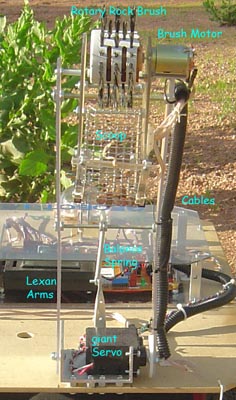
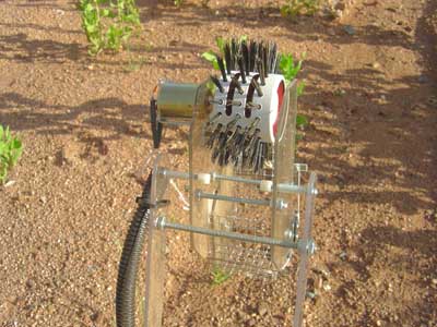
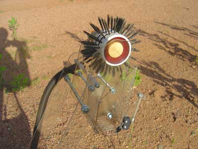
We used a large servo with a carefully counterbalanced lexan arm to put the motorized scoop on the ground. A steel spring worked very well to take the load completely off the motor and allow a fluid smooth movement down to the ground and back. A spring has the advantage of increasing its pull as the arm is lowered, and this equalizing the force the motor has to exert to lift the heavy rock scoop. The motorized brush idea has been brewing in my head for quite some time, and it was exciting to finally implement it in a working robot. The brush took quite some time to find, it is a ceramic round hair brush with long stiff bristles. We sawed a 2 inch length out of the brush and machined a hub to mount it to the 6 V DC electric motor. It takes about two seconds for it to wrap up to speed, but when it hits the ground, lots of surface material is whisked into the hardware cloth scoop cup. While I’m not going to collect golf ball sized rocks, many marble sized and smaller specimens are collected this way. We sample the ground twice on each mission, in case the first time is right on a large flat rock.
Primary Mission Scenario:
To do a mission, the distance of travel is selected from dip switches on the main processor board. We can select 0, 20, 100 feet. For our movies, to keep the size of the files reasonable, we elected to do the 20 foot run. The power switch is thrown, and the robot initializes the arm position to the "stow" position for stable travel. The processor takes an initial compass bearing reading which is maintained within 2 degrees for the travel to the destination. Essentially, the robot is pointed toward the collection area, and let loose.
The robot is programmed to proportionally avoid obstacles in its path along the way, and always resumes the original bearing after reacting to say a large rock or some insurmountable brush.
Upon arrival at its destination which is determined by total distance odometry, the robot stops, and performs the collection sequence. As illustrated above. The arm is lifted to a safe height, and the Geobot backs up about a foot. Then the ground is sampled for a second time just incase the first sample was incomplete or on top of a rock. The robot actually measures the point it touches the ground before sampling with a series of contact switches on the scoop. So what happens if the ground is NOT detected? The robot is programmed to alert the operator and wait for instructions. The arm is then stowed and the robot reverses the bearing from the original to return back to the starting point. Rotating the robot to the reverse bearing ended up being quite a mathematical adventure, you can read about it here.
The robot then returns to the home position, again avoiding any obstacles and maintaining the reverse bearing for the distance set at the time of initial release. The odometer of course resets at the destination and counts back down to zero on the return trip. Upon arrival at home base, the robot stops and waits for the specimen removal from the scoop. It is then ready again for another mission, perhaps in a new direction.
Conclusion:
The long 8 month development period was concluded with a successful series of specimen collecting missions, and demonstrated the robot was fully capable of its original design goals. From the very first time the Geobot returned rock specimens to its point of origin, to the most recent missions in and around the town of Payson where we live, it has always been an exciting achievement. While the steering and traction, and the durability of the polystyrene tank treads was not the best it could have been, it more than served the purpose of demonstration of which technologies were actually required to make an autonomous machine perform a rock collection task. We feel that we are concluding this exciting project with a very firm foundation in which to design more advanced Geobots in the future.
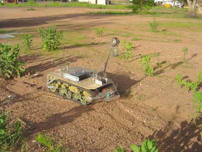
The Steps of the Sampling Sequence The Geobot at the start position, with the arm in the stow position.
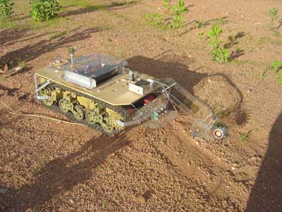
100 feet later, at the sampling locality. The arm is lowered just above the ground surface.
The arm is then lowered to find the ground, where contact switches will close and the position of the arm is recorded in memory.
Next the arm is raised again and the motor started on the brush. The arm is then lowered to take a sample. This sequence is repeated as often as needed to get an adaquate sampling of the area of interest.
Brush detail, showing the motor and collection scoop.
You can see the angled lexan cup used for storing the samples here.
movie clip here Well, this is it - the full run, showing the entire sequence of rock collection. I have the distance set for a short 20 feet, to keep the 2mb movie as small as possible. HOME