
 |
GeoBot
1
Sonar
Array Layout and Technique
Updated 3/18/06
|

|
A crucial portion
of the outdoor navigation of the robot will be a quad matrix
sonar array, which I will go into some detail of it here. For
daylight outdoor navigation and obstacle avoidance the usual
light sensing type arrays will not work in the sunlight. You
wont be able to use IR proximity or ranging, lasers are very
hard to see unless they are very powerful and heavy, and vision
based systems using CCD cameras will not be reliable in fields
of rocks that are all exactly the same color on a cloudy day
with no shadows.
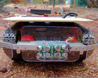
The first part
of a solution to outdoor navigation for our robot was to install
extremely durable high impact instrumented bumpers on the front
and sides. The second phase of protection and direction seeking
will in in the form of an array of 4 sonars projecting a specific
pattern interpreted by a dedicated PIC processor as to not load
the main controller. Here is a photo tour of our method, and
some diagrams and schematics to follow on.
|
| The
best configuration for a mapping sonar system such as this will
be as close to a point source as possible as to ensure proper
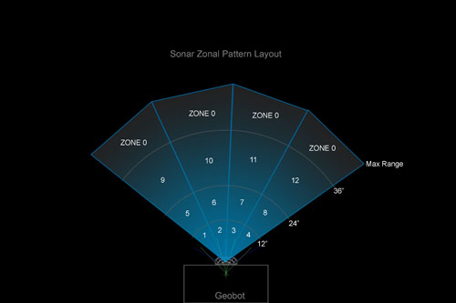
overlap of scan sectors and a bare minimum of dead zones. Our technique works like
this: for sonars with approximately 30 degree patterns (we measured
about 25d) are mounted in a small as possible array on the front
center of the robot. Each in turn sends out a sonar burst and
receives its return before the next one in line is fired. The
whole scan takes about 1/4 second. The sonars beam is divided |
| into
four zones according to the distance measured. 0 - 12 inches
for example are the first zone out, and the second at 12"
- 24". The third zone is at 24" - 36", and finally
anything beyond that we really don't care about for our purposes
and is classified as the general zone 0. Using this zonal approach has many advantages
and can generate complex movements amongst obstacles with relatively
simplistic programming. The greatest dangers lie closest to the
array, and thus have priority over the more distant obstacles
and thus we use priority arbitration to control the robots response
to the range of zonal dangers. |
| So
here is how it works. Three rocks which are too big to drive
over are within the sonar arrays range as seen here. But which
one to act upon? Will it be the huge rock to the right but far
away, or the close small one which is about to strike the robot
and in its path? The
sonar processor uses priority arbitration architecture to ferret
this out, and reports via serial or parallel lines to the main
processor | 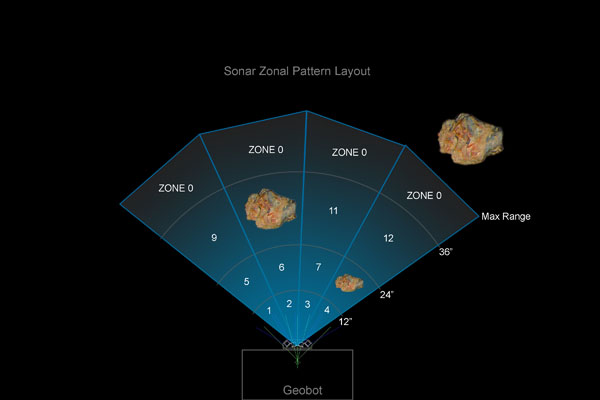 |
| the
obstacle of GREATEST danger to the moving robot.
In this case, the small rock is the danger, and zone 8 will be
reported to the main controller. |
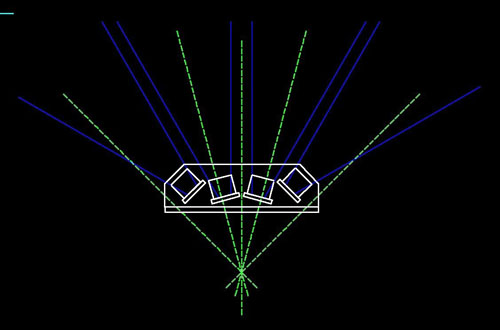 | Enough
of theory, lets make this thing. Rather than a hemispherical
shaped housing to hold the sonars which was way to big to be
mounted on the bumper, a very CAD optimized shape was created
out of lexan as seen here. The sonar barrels are mounted vertically,
spaced at exact 30 degree spans, and were offset both in X and
Radius to create the compact housing shape seen here. This housing
will have to take rock impacts because its on the bumper, so
must be very durable! |
| Here
is the final scale drawing of the array from the top. the entire
4 part array is just over an inch deep, and only 4 inches wide. | 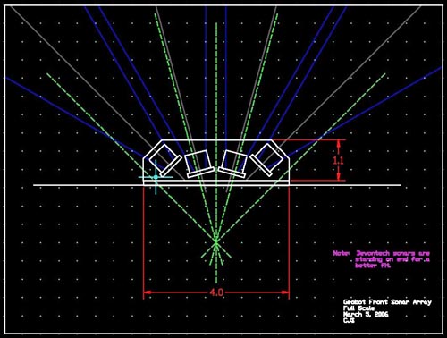 |
 | Machining
the housing per drawings, we found it made an attractive yet
functional bumper addition. The wires bundle goes through a hole
in the bumper, and routes up about 16 inches later to the sonar
processor through flexible tubing. |
| Top
view of array on bumper. | 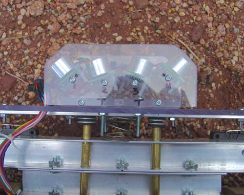 |
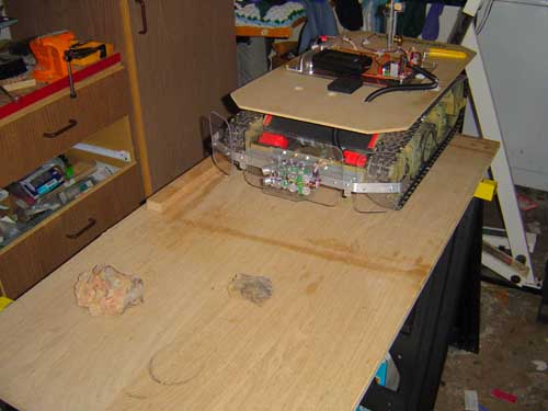 | First
bench testing on a flat surface with REAL rocks revealed a critical
balance between detecting the ground as a reflection and an actual
rock. The angle of the array was adjusted vertically as to pick
out a 2 inch rock at all positions to avoid dangers. The ground
reflections on gravel made for about a 2 - 4 foot reading. |
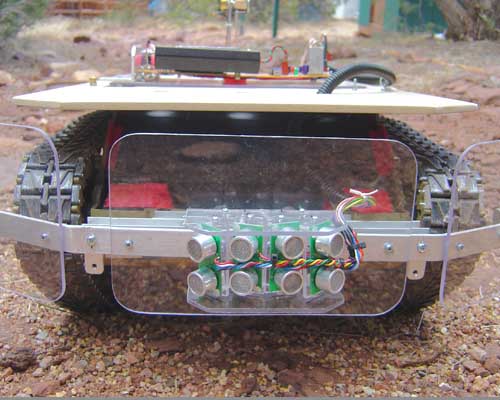
| The
sonar chip is the one to the lower left of the main 16F877a processor.
I've hooked the LCD display to it directly to be able to see
whats being seen by the 4 sonars. There are two rows of four numbers on the
display. The top row is sonars 1 - 4 actual inches display from
the nearest reflection. The bottom row is the same data, but
displays the zone number of the corresponding reflection. These are the numbers in
which the Priority Arbitration architecture will deal with. | 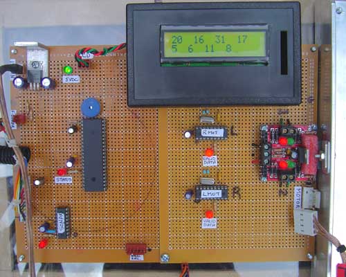 |
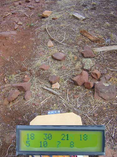 | Out in
the field, here is a sample reading as it is moving toward the
rock pile. I've enlarged the display and superimposed it on the
robot for clarity! Obstacles
range from a cozy 30 inches out, to 18 inches. The choice here
would be to veer left, to avoid the two closest obstacles. Choices
for the different zones will be different. For the closest zone
(all sonars) we would have to stop, then look for the clearest
path out. For the second zone, we bank right or left while moving,
the third zone means to veer right or left gradually using the
PWM differentially. And finally, zone 0 means keep going. |
| Here
is the schematic for the sonar processor. You can of course click
on this one to make it much larger. | 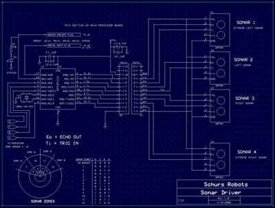 |
HOME
You are visitor
number since June 17, 2001

FastCounter
by bCentral