Here we will show the new tank tread odometer for the Geobot, and a brief discussion on the Priority Arbitration Architecture that is in the process of being implemented in this totally outdoor robot.
Outdoor Odometry
Both wheeled and tread driven robots that must function in the rough and rocky outdoor environment face a similar problem of precise odometry for distance and navigation. Not only do wheels slip differentially when trying to go straight, the rough ground can cause one side to travel a very distance than the other. Even after a moderate distance of ten feet, our experiments show the robot can be more than 30 degrees off from its initial starting orientation. Over rocky surfaces, the problem is amplified when one wheel or track goes over a base ball sized rock or mound while the other does not, causing a swerve toward the side the rock was on. For our project, which the Geobot will be traveling over golf ball to baseball sized rocks in a field of gravels and large boulders to get to its destination, navigation by odometry alone will never get you there.
For our purposes then, we will monitor one side only, and use that as a rough guide to the total distance traveled toward way points. At that time, additional sensors will be used to refine the position.
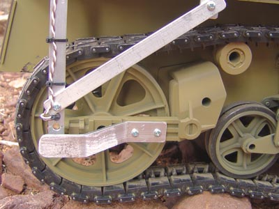
In our concept, the rear tread wheel is used to determine distances. Here, we project a modulated IR beam several inches through the spokes in the wheel and the receiver puts out a high on detection of a spoke. Each spoke counts 2.6 inches, and 45 spokes marks about 10 feet total travel.
The 914nm LED is mounted on a bracket that hangs down from the bottom of the top board. A diagonal brace adds rigidity, and a rock deflector is on the outside to keep boulders from smashing the assembly.
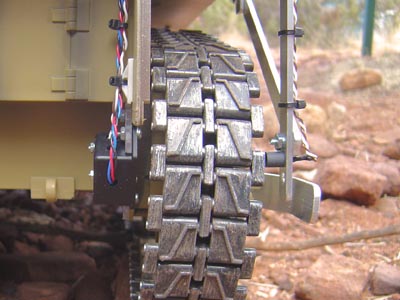
Rear view showing the wiring for the sensor goes through the top board and down to the receiver box.
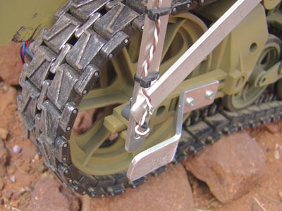
Here is the best view of the setup. The IR LED on the right is in the short black tube. It projects a strong beam through the spokes in the wheel and into a black plastic box on the other side. The PCB we made contains an IS417 circuit which we will detail later. We can take direct sunlight on both transmit and receive assemblies because the IR is modulated and constant DC sunlight is ignored.
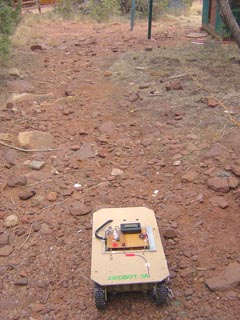
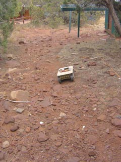
Demonstration outdoors through a run of large baseball sized rocks. We aim at a distant spot, and instruct the robot to go 45 counts = 10 feet.
This is where the robot stopped. Now you can see that in only 10 feet, the robot is not pointing at the target anymore and in fact is at least 10 degrees off course. On a flat level surface, such as a roadway, the robot goes very straight. But here with the rocks moving under each tread differently the end result is a deviation from the original trajectory. Later, we will be adding a digital compass to keep it re orienting itself periodically on the way to the goal.
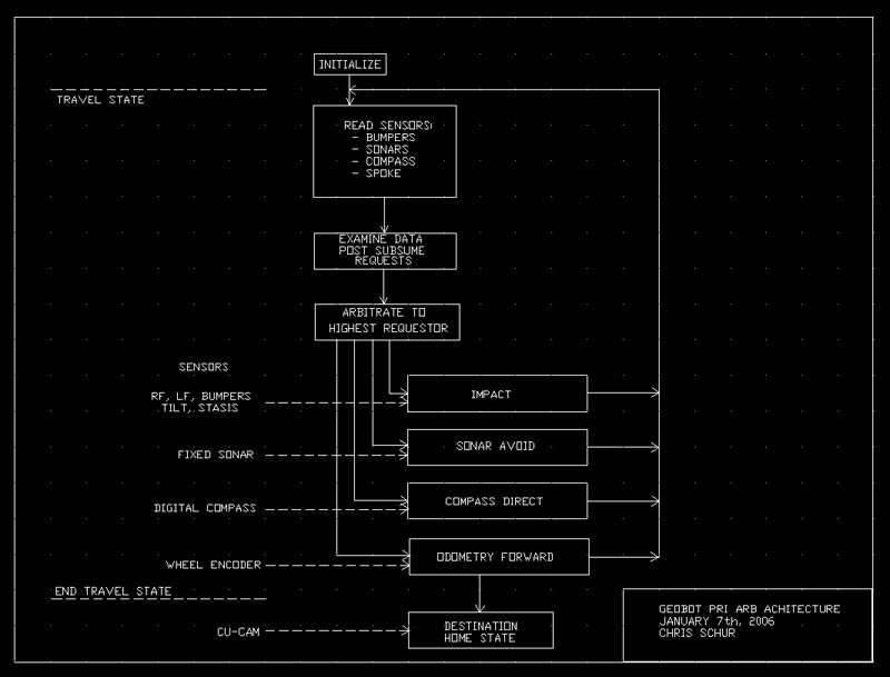
With a single processor (PIC16F877a), to implement any form of layered behaviors in an architecture requires very careful planning, and a tidbit of a technique for programming I learned from a recent issue of Servo Magazine. To do a layered simultaneous architecture requires the following method. We will be using it as a sub unit within a much larger Finite State Machine layout, and only for the travel to destination portion only. Layered behaviors are great for being very robust at getting you to your final destination, however we will be jumping to a standard FSM for the task at site programming. Thus this hybrid approach we are calling "Finite State Priority Arbitration Architecture".
A brief explanation
After the robot is initialized and obtains its mission, it travels to multiple way points to reach its final goal to dig or collect specimens. The travel part is the subsumption part of its program. When running this loop, remember nothing can take any significant time. No operations that take many seconds in the loop are allowed. Here is the process:
- Scan all the sensors and store in variables.
- Each behavior examines its pertinent data and determines if it will request to subsume.
- The Arbiter merely looks at all the subsumption requests and picks the highest priority.
- The behavior is run, and the drive motors or other outputs are changed to the behaviors control
- We then go back to the start of the loop and resample the sensors again.
Once the odometry is satisfied that we have traveled the required distance to the goal we jump state to the destination homing state to refine the position near the destination marker or beacon.
At this point, with the bumpers, and odometer as the only inputs, the architecture is running fine. We are adding a tilt sensor next to keep from driving up too steep of a slope. Stay tuned for further developments!
HOME