|
In this chapter
we will discuss the optical sensing techniques that will be integrated
into the robot itself, to enable it to locate and successfully
dock with the charger beacon. There are two steps involved with
this process. First, the robot must become aware that it is within
range of the charger beacon with a non directional Omni type
sensor that will detect the beacon no matter which direction
it is relative to the robot. This is called "Proximity Detection".
Once the robot has determined it is near the charger, a less
sensitive narrow angle sensor allows it to home in on the beacon
and direct it to the charging base. This is called the "
Directional Sensor". Here we will cover both topics, and
give you a sense of the approaches that are commonly used to
get our bot to its base. In these diagrams, sensors are usually
color coded red, as is the source IR beams.
Proximity Detection
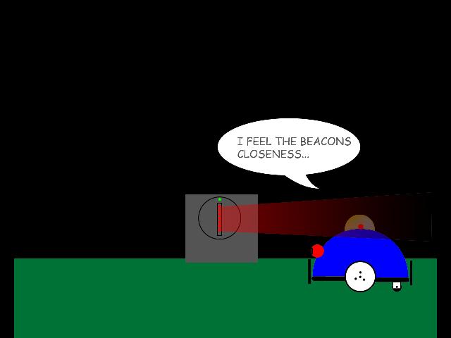 | A
very simplistic approach to proximity detection is to enclose
a sensitive IR detector inside a translucent dome. When the surface
of the dome is struck with infrared modulated light, the sensor
will see the domes underside light up and a crude detection is
accomplished. While fairly low in sensitivity, if one uses a
Panasonic PN4602 integrated sensor, the range can be six feet
or more in a normal room brightness. |
| An
overhead view of how this works is seen here. The beam will sweep
over the robots central detector as the robot moves forward only
when it is within the narrow confines of the beam. The robot
would then immediately stop, and start its routine for determining
the beams point of origin. | 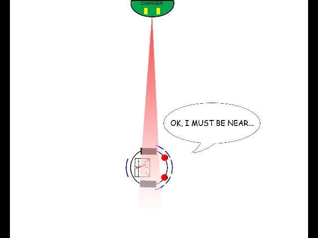 |
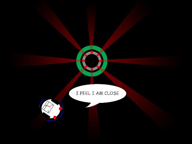 | With
a centrally located multi-beam array on the beacon, the robots
chances for detecting its proximity to the charger are greatly
increased. Such an extreme approach is suitable for office or
factory environments, however the single beam is more suitable
for a home environment. |
Directional Sensing
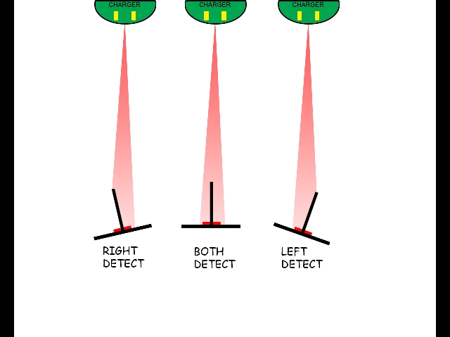 | This
is how the basic analog and digital vane sensors work. When the
vane points to the left of the beam, the right side is in the
light and the left side is in the shadow of the vane and sees
no light. By rotating the vane back and forth by rocking the
body of the robot or moving the sensor on a servo motor, we can
determine when the vane is directly aiming at the source when
both sensors just see light at the same time. In the case of
an analog system, cadmium sulfide photo cells can give a linear
voltage reading which indicates the source direction by comparing
the two output voltages. For a digital sensor such as the PN4602,
when the vane is exactly pointed at the source, both will have
an output. Proper filtering of the digital outputs is ESSENTIAL
for giving the microcontroller a clean signal. More on this later. |
| Another
type of directional sensor used is the tube type. Here, a single
photocell is mounted at the bottom of a black tube. Only when
the tube is aimed directly at the source will there be an output.
The robot then rotates 360 degrees slowly and when the beam is
detected stops rotation. It then drives forward until it looses
the beam, then does its search all over again. This simplistic
approach can work fairly well, but the robot uses up a lot of
energy spinning every few feet to get to the charger! | 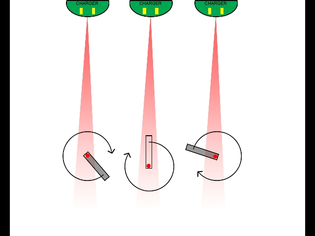 |
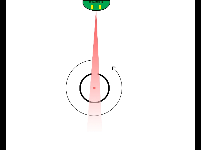 | A
rotating cylinder with a single photocell in the center or back
of the tube opposite of the slit can also be used to locate the
beacon. The idea is either the entire robot or just the cylinder
rotate, and when the slit in the side of the cylinder is aimed
exactly at the source, the photocell will become active. I rather
like this approach because the cylinder can be easily turned
by a servo, and the slit can be so narrow as to get directional
accuracy needed for a precise navigation to the charger. |
| An
example of a four way vane sensor in action. This was one of
our experiments with the PicBot5 and provided first, an crude
direction for the robot to turn, and second the vanes can be
used with two of the sensors to home right in on the robot. Later
we will have lots of images and some movies of this technique
in action. | 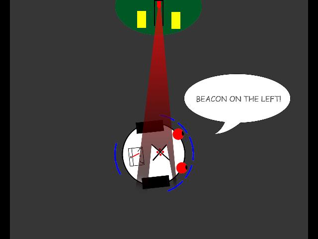 |
| With
an analog approach, and two IR phototransistors, we can simply
measure or compare the voltages from two sensors mounted about
where the eyes are in the graphic on the right. You can either
use a compartor to do the comparison and put out a digital signal
to the processor or send both analog voltages directly to the
analog in ports on the micro. | 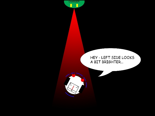 |
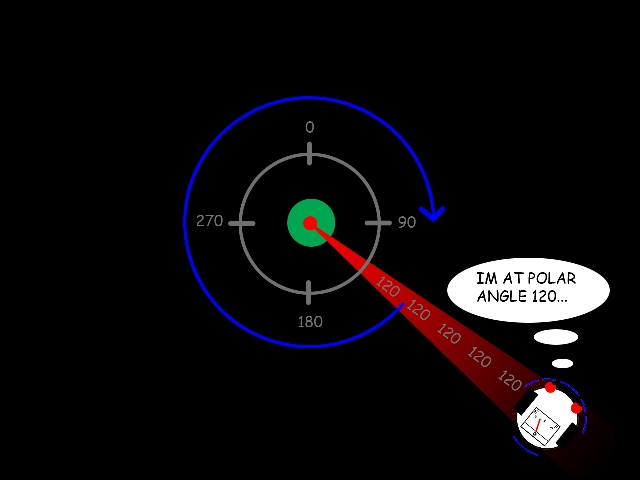 | A
very cool approach to beacon location is to rotate the IR beam
on the charger, and encode its rotation angle in the data stream
on the IR beam. The robot then knows its polar angle from the
charger and perhaps using sonar can get the radius to the charger
to get its exact position in the room. |
| The
"Roomba" docking technique is to encode in the beam
what the robot should do if it encounters the beam. So the robot
will drive along, into one of the side beams and start turning
toward the charger as it is instructed to do so. Such a system
must be perhaps in a hall way to limit the robot so it does not
cross the center beam first. | 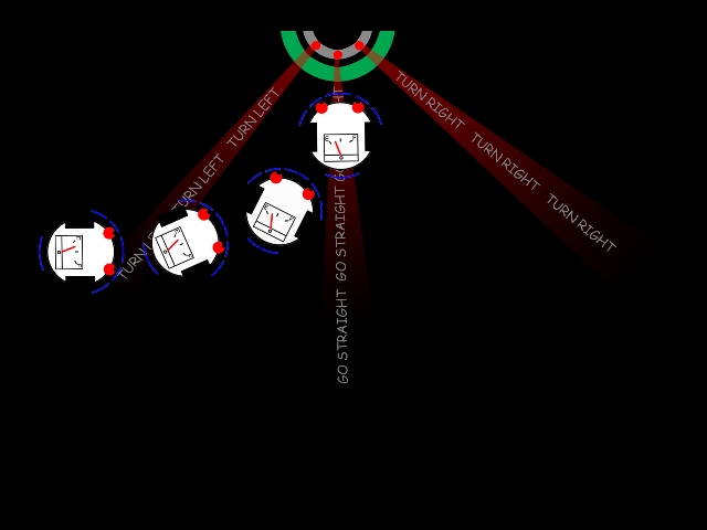 |
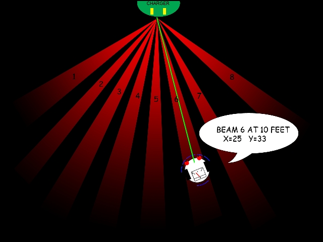 | Another
thought at encoding the beams with data, if we simply number
the beacon beams which are active all of the time, we can get
directional information to the charger. This allows us to COMBINE
a charger beacon with a complete navigation system in a small
room or office area in one unit. |
|

HOME