|
At some point in this article,
we have to support the theoretical discussions with actual results
from the laboratory. We spent many hundreds of hours on designing
and performing docking experiments with the PICbot 5 unit, which
was typically rebuilt every time down to the bare chassis for
specific experiments. Were going to take each lab example one
at a time here, and go into great depth on the techniques and
hardware used to make a real world robot actively seek and dock
successfully with its battery charger.
About the Robot.
PICbot 5, which
is the fifth in a long series of PICbot articles is essentially
a bare stripped Boe Bot chassis, with serially driven home brew
servo driver PIC processors that are commanded by the test processor.
In most cases, the processor was either a 16F73 or 16F876A Microchip
PIC, with a total of 28 pins. These controlled two 12F629 home
brew RS232 servo drivers and completed the intelligence section
of the robot. All of our programming was done in PICbasic Pro.
For power, 8 AAA NiMH batteries were used to power both the motors
and experiments. Two push in type proto boards rode on the top
of the robot for quick changes to the hardware, and we also put
in a Scott Edwards serial LCD for communication from the robot.
We will break down
this rather large section into Detector testing, Proximity, precision
alignment, and docking contacts. We'll also throw in any schematics
or drawings as needed. Finally, we will summarize our Lab results
and suggest where to head from here.
Section 1: IR Range
Testing
Testing the PNA4602
Sensor
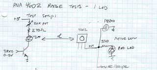 | First,
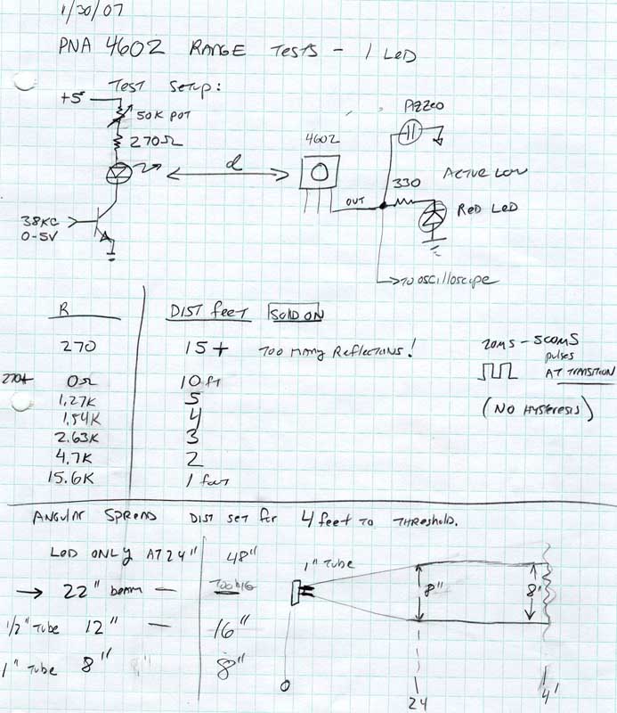
lets go over the basic beacon circuit we are using. A 38.5 KHz
source coming from a precision function generator drives the
NPN transistor for modulating the IR LED at the correct rate.
In our test circuit, I've also added a 50k pot for brightness
adjustment for range testing. This signal is received by the
Panasonic PNA4602, which drives both a standard red LED and a
Pizzeo speaker to hear the switching noise. |
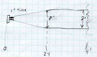 | A
suitable narrow beam pattern was obtained by installing a 1/4"
diameter tube that was one inch long over the IR emitter. A beam
spanning 8 inches wide at its fullest resulted in this way, as
detected by the PNA sensor. |
 Click for a larger view
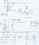
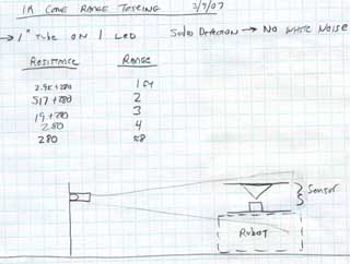
| Our
notes on range testing. In a nutshell, for a four foot range,
a 1.5k resistor was used, When the power was high, such as when
we used a 270 ohm, the reflections off of the inside edges of
the tube and distant walls made the measurements very difficult.
Keep your power low, and limit your range to less than 10 feet. |
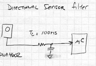 | A
VERY crucial part of using the PNA sensors is to filter their
digital output with a low pass filter to control the rapid transitions
that occur at the switching points. Your robot will encounter
many instances where the beam is only partially detected such
as in vane homing. The slamming square waves that result will
totally confuse the processors. So we did numerous experiments
to determine how much filtering was needed and yet still give
good overall response. |
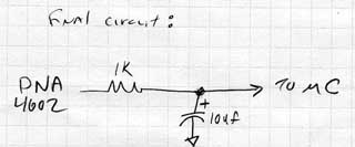 | The
resulting values were 10 uF for heavy filtration, and 1 uF for
most applications. This is what we used for the testing. |
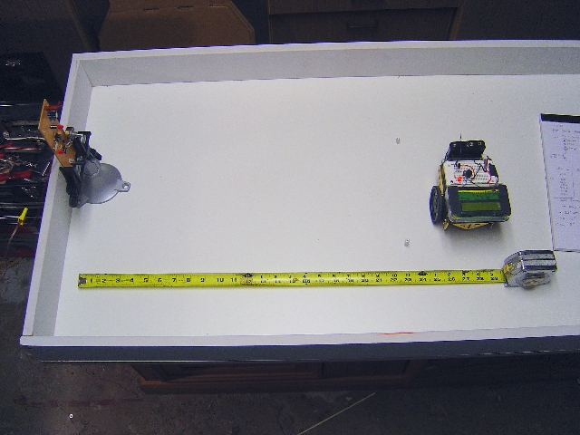 |
Range Testing.
The robot was moved
back and forth to determine the range of the PNA sensors with
the beacon set for different drive levels. We were able to adjust
the detection limit from about 6 inches out to over 10 feet,
well past the ends of the Robot Arena.
|
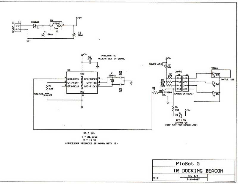
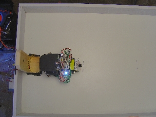
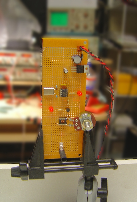 | The
bare Beacon with the IR LED at the bottom in a black tube. The
range pot is below center, and 5v regulator at top. We used a
small PIC for the 38.5k source as in the schematic below. |
 Click for a larger view
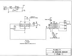
| Schematic
of the beacon. A 12F629 PIC processor was programmed to simply
go high and low at the correct rate to generate the square wave
form to drive the IR LED. This was accurately measured and tweaked
with a frequency counter as well. A 10mhz xtal was used for stability. |
Section 2: Proximity
Detectors
Building an Omni
Cone Sensor
Warning:
Heavy Math Ahead!
For those of you
that are versed in geometry and trig, we will share our notes
with you on the design process for designing a very accurate
omni cone. For those of you not interested in the math, we provide
the dimensions at the end in the drawings for you to copy and
make a cone like ours.
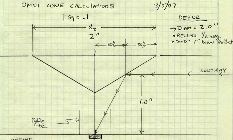
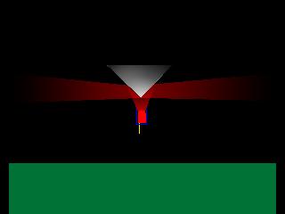 | Basic
concept of an omni cone beacon, or IR receiver assembly. Light
from the modulated IR LED shines upward to the cone, and is diverted
exactly at right angles to the surface to reach out across the
room in all directions. Similarly, if the LED here is replaced
with a PNA4602 sensor, it can become a very wide angle proximity
detector on the robot as well. |
 Click for a larger view
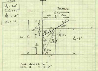
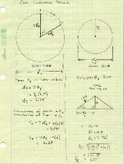
| Lets
start with a basic definition of our side view of the cone, with
a few dimensions we wish for the final design. |
 Click for a larger view
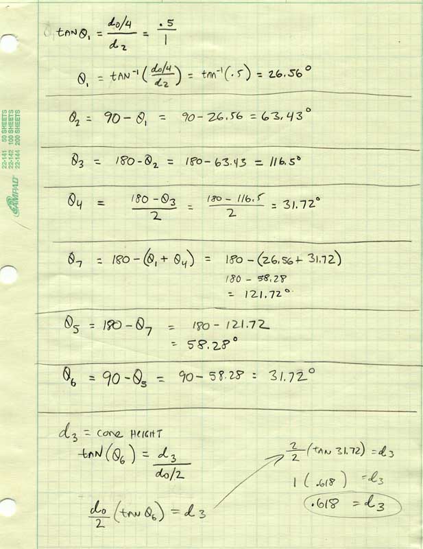
| Breaking
it into a geometrical concept, I've labeled some of the angles
and dimensions we will be calculating. Note the "Defines"
in the upper left, that is our starting points. |
 Click for a larger view
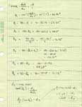
| Next
we calculate each parameter in the geometrical concept. |
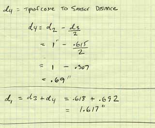 | d4
allows us to see that our sensor to cone tip is about .7" |
 Click for a larger view
| And
finally, with all the numbers, we actually have to MAKE the cone.
I spent quite a few hours pondering this one! Here is my mathematical
technique, you make a disk out of the reflective material (discussed
later) and cut a pie shaped wedge out of it. The cone is then
folded to the cut outs to make the 3D shape. Pretty cool, ay? |
 Click for a larger view
|
Preliminary
cone tests
Range was considerably
reduced when working with a cone rather than directly with PNA
sensor looking right at the beacon. About half the range resulted,
with the center of the cone the same height as the beacon LED.
|
Making the cone,
step by step
Here is a photo
pictorial of how we made our cones for testing. The material
was a very highly reflective mylar coated poster board material
obtained at a craft store for about $30 for a big 2 x 3 foot
sheet. Many years supply for making cones!
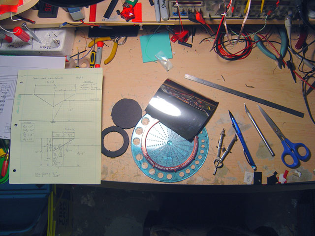 | Laying
out all the tools for the task. A precision protractor and compass
are a must, and sharp razor cutters for trimming the exact angles
as well. |
| The
disk was cut out of the mylar board, and the angle of the pie
shaped cut out drawn in. Using the blade, we cut out the wedge
from the disk. | 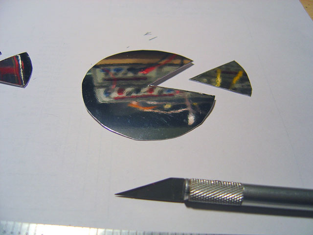 |
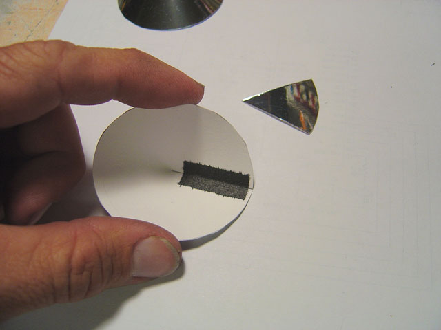 | From
the rear some cloth tape sealed the seam to make the 3D cone
a reality. |
| We
then dropped the cone into a base made from foam board that was
the same diameter as the cones base. This holds it round and
symmetrical. |  |
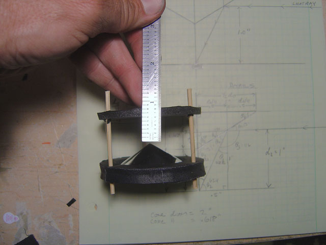 | Three
struts were added around the cone, and the top sensor disk was
set for the .7" spacing + the thickness of the sensor. |
Testing the Omni
Cone Prox Sensor
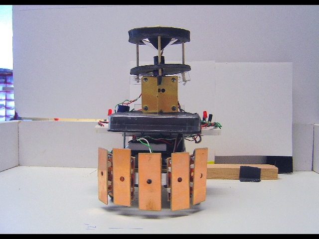
 | The
omni cone mirror assembly mounted on the top of the PICbot V
platform. A laser was mounted in a vice and pointed exactly level
at the center of the cone. The reflection should hit exactly
in the center under the cones tip if we did our math right. |
| Mathematical
triumph! The laser strikes the point under the cone no matter
how the cone is rotated. In other words, you can spin the
robot and the beam always hits the exact center of the bottom
disk. | 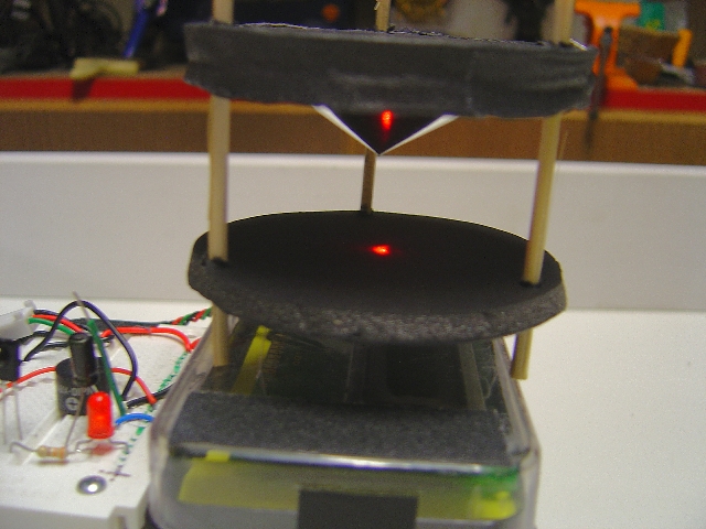 |
| Shining
a bright light on the cone, we can see the sensor inside the
short black baffle tube from any angle. No matter how you rotate
the cone assembly, you will always see the reflection of the
sensor like this! | 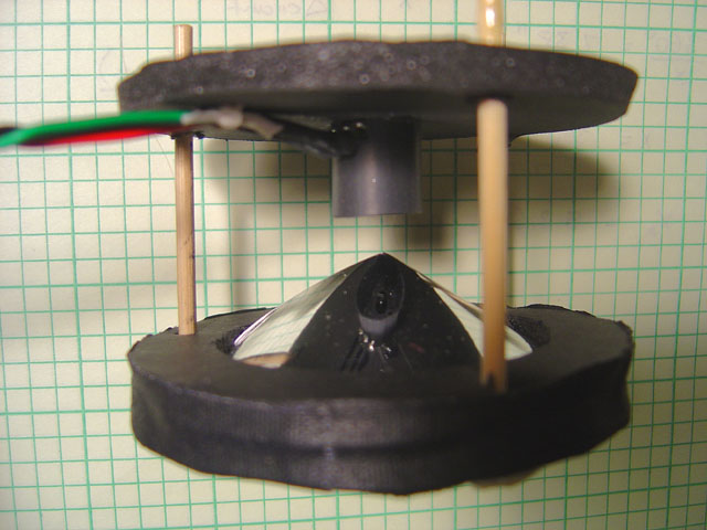 |
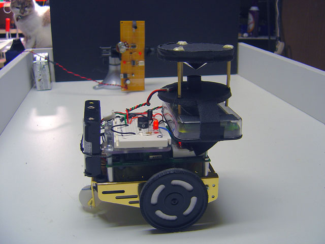 | PICbot
V ready for omni cone proximity testing in the robot arena in
our lab. |
| Range
and angular detection testing. The robot is programmed to go
straight until it detects a signal in the omni cone proximity
sensor, then stops. We can then measure the response and acceptance
thresholds for the device. | 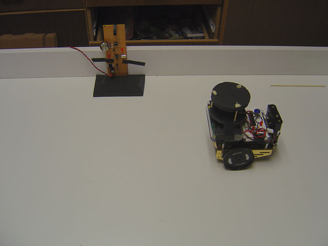 |
 Click for a larger view
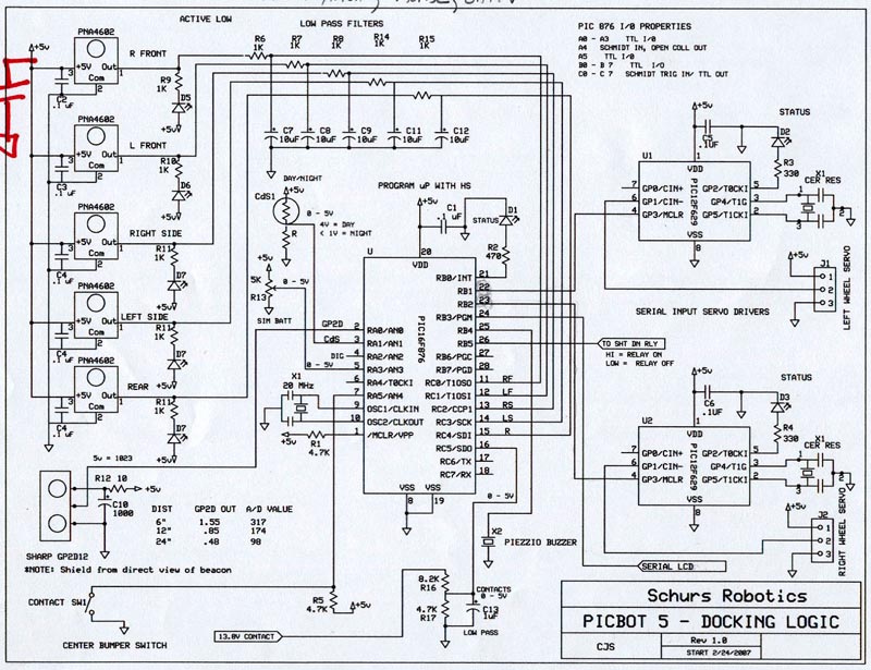
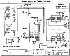
| PICbot
V schematic diagram. A 16F876a main processor drives two smaller
servo driver processors we designed to operate with RS232 data,
and take the data from all the sensors. |
The 4 way Prox
Sensor Array
Another type of
proximity sensor we tested was a 4 way vane type. Here, four
PNA detectors were mounted at the vertecies of an X shaped arrangement.
The effect was to have one in the rear and front, and one on
each side. In this way, we can not only tell in a 360 degree
range there is a nearby beacon, but approximately on which side
of the robot.
 |
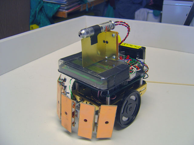
Vane
sensors mounted on the robot. You can see them as small black
PNA sensors mounted in between the white cards we used as vanes.
So here, the left side is covered by one sensor, with nearly
no overlap with the front and rear sensors giving us some indication
of the direction of the beacon. |
 Click for a larger view
|
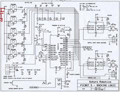
The
complete schematic of PICbot V with the vane proximity sensors. |
Section 3: Precision
Alignment Sensors
Building a Vane
Type sensor array
In this section,
we will go step by step on how to construct a very accurate positional
vane type sensor. You know from the theoretical diagrams we showed
you earlier how they work, and now lets put that design to a
practical application. Remember, the vane sensor is used to actually
point the robot and guide it right to the beacon.
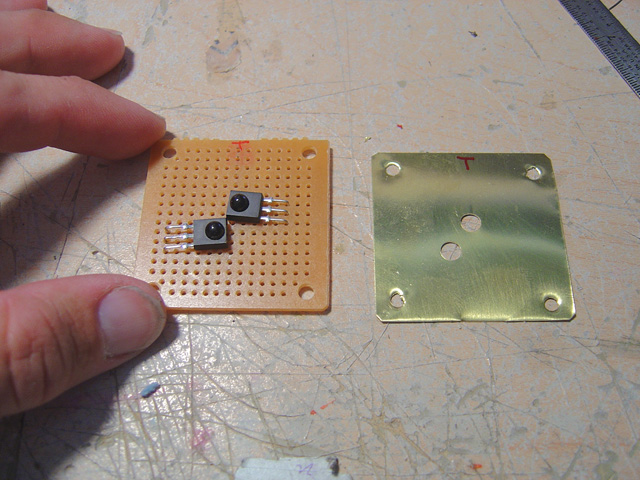 | Two
PNA sensors are mounted like this staggered to get the sensory
chips as close as possible on the horizontal plane. A mask, made
from brass here is carefully drilled to match the lenses. |
| When
the brass mask is over the sensors, only the lenses protrude. | 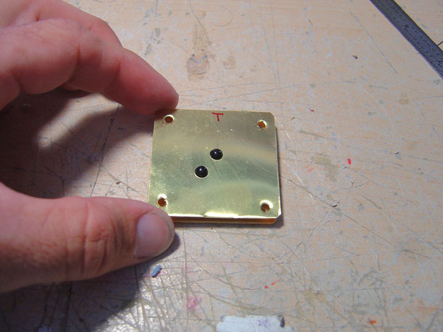 |
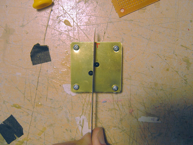 | Laying
a metal scale between the lenses shows how close they are to
the vane. This will give us the maximum resolution in pointing
at the beacon. |
| The
actual vane, here about 2 inches long is soldered onto the mask,
and at an angle of exactly 90 degrees. Now you can only see one
sensor at a time. | 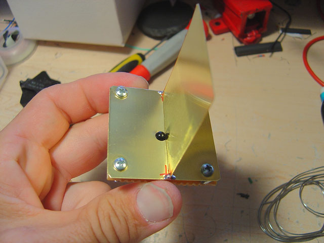 |
 | From
the top, we can see the perfect perpendicular angle of the vane
relative to the base. I used a square when soldering to do this. |
Testing the Vane
Sensor Array
 | Mounted
on the PICbot, and wired into the processor, we can program the
robot to report the position of the beacon by merely examining
the sides the sensors are active. And once again - make CERTAIN
to always include the RC filter in the outputs of the PNA sensors
for crisp clean outputs. Here both sensors are active because
the beacon is exactly straight ahead. |
| The
left sensor is active, and right shadowed. So the robot reports
the beacon is on the left. | 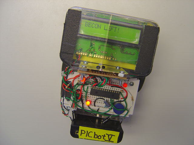 |
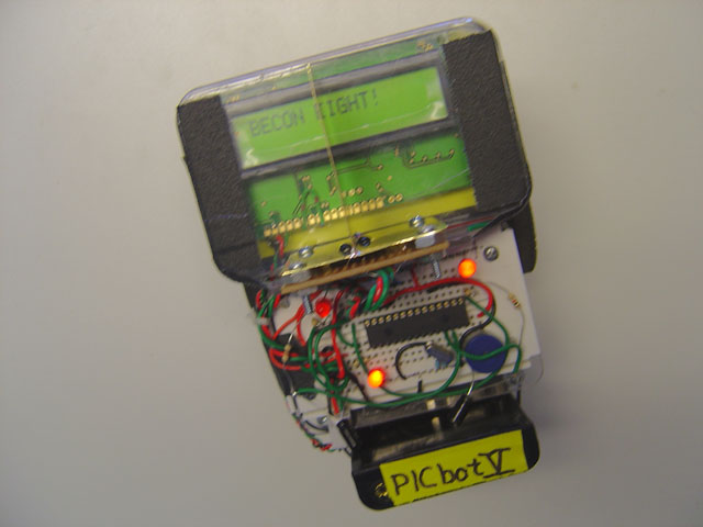 | Now
the right is active, and left shadowed. |
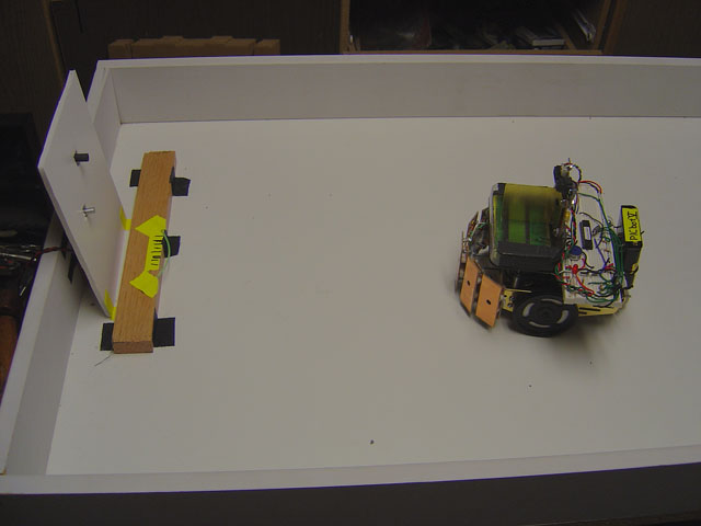
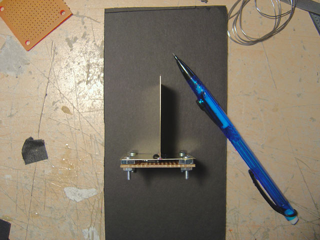
| For
our precision aiming tests, the setup included the beacon mounted
behind a white board with the LED tube and pot sticking out for
brightness adjustments. A wooden stop prevents the robot from
ramming the board. | 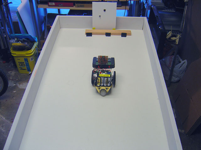 |
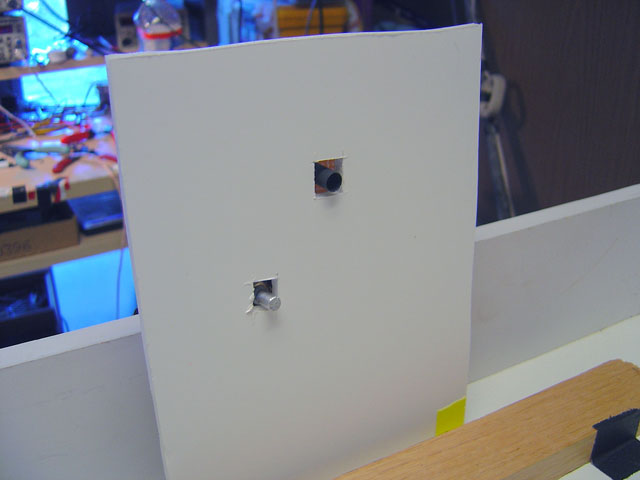 | The
test beacon close up. |
| From
the front, the central vane is nearly invisible, and we can see
the two sensors ONLY when the vane is aiming exactly at you. | 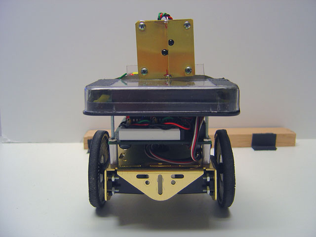 |
 | By
attaching a laser to the top of the vane, we can see where the
robot is aiming when it homes in, to determine its wobble and
pointing accuracy. |
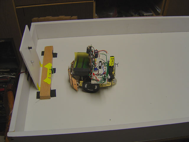
| The
laser in action. Here, the robot moves towards the beacon defining
a somewhat jerky "S" shaped path. The beam will sweep
across the beacon but is centered dead on target. This was instrumental
in allowing us to determine how the vane length affected accuracy. |  |
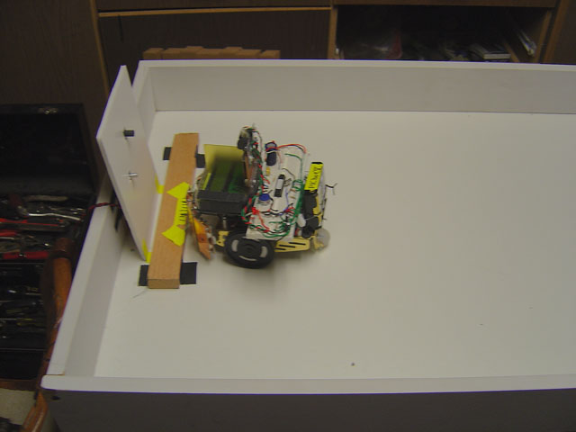
 | The
robot stops at this point in the test on the bumper stop, aiming
exactly at the beacon. The bumper impact stops the wheels during
each test. Accuracy was determined by the spread of contact points
along the wooden beam. |
Docking sequence
three part pictorial.
To determine the
docking accuracy of each sensor/beacon combination, the robot
was programed to drive to the beacon, and stop when its front
bumper touched the wood slat. The position of impact was marked
and another trial was performed. After many trials, the range
of contact points became well established.
|
Movie
1
PICbot V acquires
beacon with the precision detector, and drives to the test base
as seen above. This is a short movie.
|
Movie
2
A pretty cool short
movie, showing the robot homing in on the beacon with the laser
on its top pointing in the same direction as the vane in the
precision sensor. Watch the red dot on the target!
|
Combining the Sensory
Arrays
Proximity Cone
+ Precision Vane Sensor
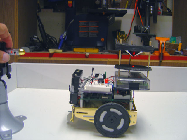
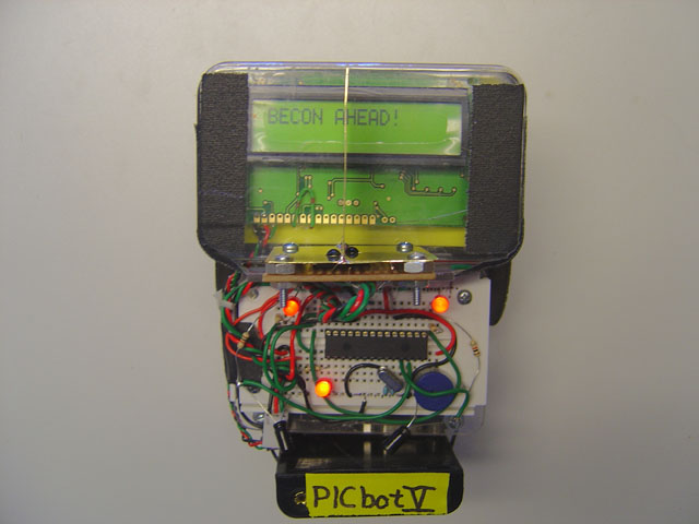
 | The
robot in its test configuration. On the very top is the Sharp
IR range detector to measure the distance to the beacon housing.
You'll recognize the Omni Cone sensor below it, sitting on the
vane type precision direction detector sensor. The LCD display
allows us to monitor what the robot is currently thinking, and
the last sensor array is the bumper ring you may recognize from
the PICbot II program. |
 | Frontal
view showing head on - this is the view the beacon would see
if the robot were approaching. |
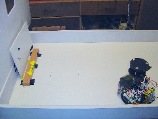
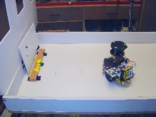
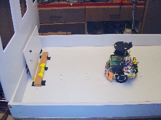
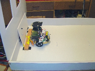
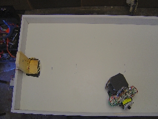
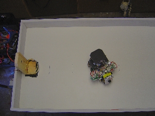
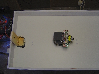
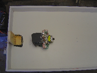
Docking sequence
from a movie showing the robot driving at an angle into the beam
in frame 1, Omni cone proximity detection and stopping in frame
2, Precision acquisition frame 3, the drive in frame 4, and finally
docking frame 5.
|
Movie
3
| The
movie of the above sequence, note also that the robot rotates
a full circle to look for the beacon after it stops initially
to get a lock on the beacon. Also very critical - the robot slows
down to half speed when it gets within about six inches of the
beacon. |
Section 4: Docking
Contacts
Docking with Dual
Hoops
Now were adding
some "REAL" electrical contacts to the lab tests. One
of the most successful contacts was the dual docking hoops. The
front of the robot has a modified bumper with a split copper
plate on the front to contact each hoop with the 12 volts of
charger voltage. You will now see when the robot docks successfully,
that I've put a brilliant white LED on the e robot to show it
has made electrical contact, seen well in the last frame here.
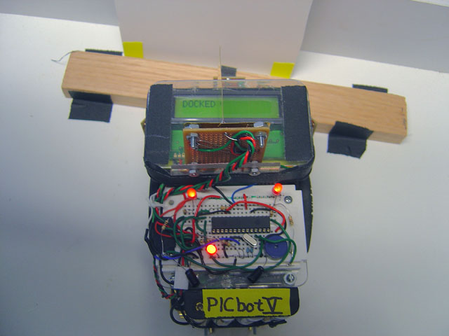
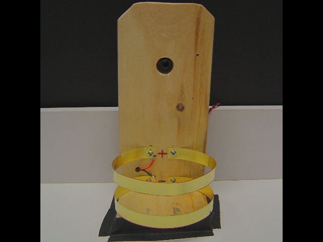 | The
test charging beacon consists of a base with the IR beacon at
the top, and dual spring loaded opposite polarity charging hoops
at the base. The hoops are made from brass strips about half
an inch wide and a foot long. |
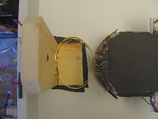 | On
a direct drive in, when the robot touches the hoops, they compress
slightly making a perfect contact with both upper and lower bumper
plates. The acceptance angle is huge, and allows for success
in docking better than any system we tested. |
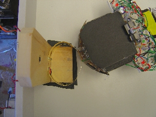 | Coming
in from the top, you can see the hoops still conform to the front
of the robot. |
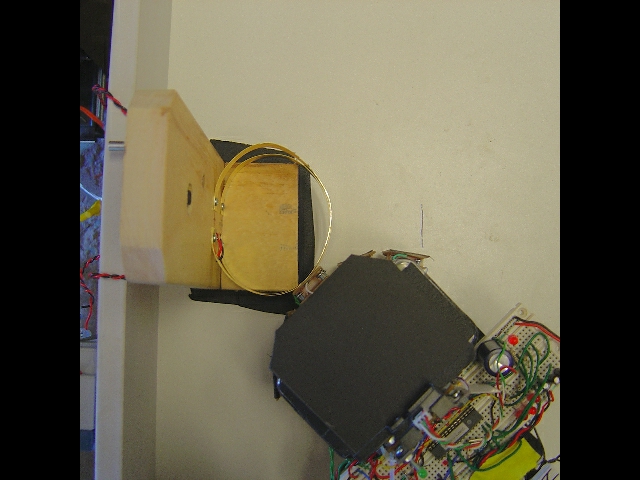 | Any
angle within a 90 degree range will dock just fine. Making this
the best and most versatile system for docking contacts. |
|
Movie
4 | This movie shows the robot docking with
the dual hoops with its usual success. I've now added a potentiometer
to the back of the robot that allows me to dial in any battery
voltage level I want into the robots battery sense inputs. When
the robots battery is above 10v, the robot sits still and allows
what would be a higher level of priority programming to do its
task. When I turn the knob to less than 10v, the robot takes
off and docks. This is because now the priorities have changed,
and the prime task is to recharge. |
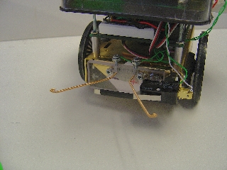
Docking with Flat
Charge Plates
For this method,
a flat panel with two foil plates with opposite polarity was
mounted on the charging base. The robot was then equipped with
two short whisker type contactors, and a bumper contact between
them for testing. Here are our results of this technique.
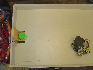
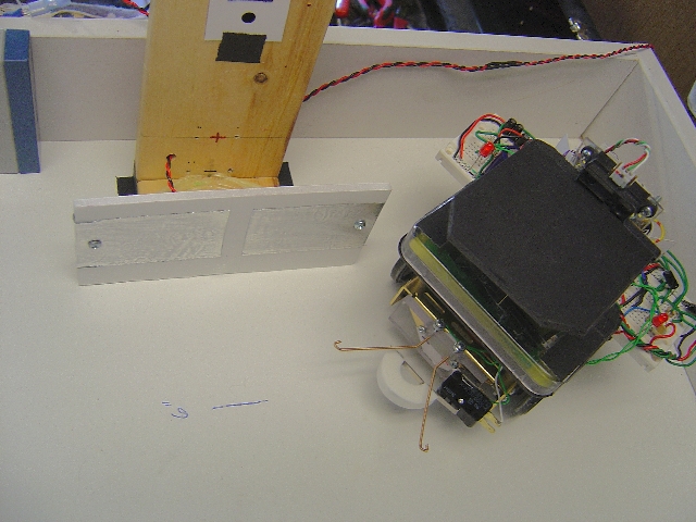 | The
flat plates on the charging base, and robot. Note that the omni
cone has been removed, since we are mainly concerned with the
actual docking performance. |
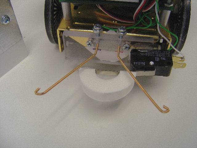 |
The front
of the robot has to brass wound guitar strings for contacts,
and a lever switch with a foam bumper between to tell the robot
when to stop should it not see any electrical voltage first.
|
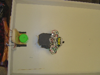
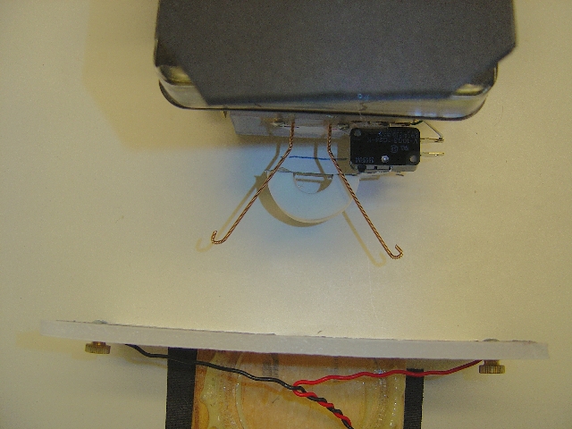 | From
above the plates, we can see as the robot heads in, the whiskers
will each touch their own plate. This works very well when straight
on, and becomes less effective at steepening angles. Limiting
the beacon angle to fairly narrow will take care of this for
the most part. The advantage of this system is fairly obvious
- extremely compact, and can be wall mounted anywhere. |
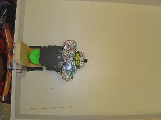
|
Movie
5 | This movie shows the robot acquiring the
beacon, and driving right in to the plates. Take a good look
at this movie - this is the easiest docking station we have made
yet and you may want to use this design. |
Docking with the
Whisker Cylinder
A variation is
to wrap the electrical contacts around a cylinder and connect
with brass whiskers.
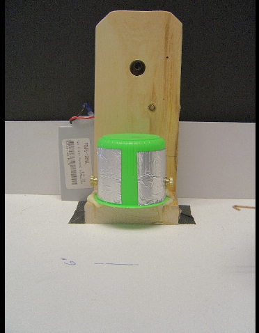 | This
docking station shows the beacon at the top, and the cylinder
which was a spray can lid wrapped with the foil tape. Screws
on the sides allowed us to attach wires to make the electrical
connection. |
 | For
this arrangement, the foam bumper was removed and replaced with
a rubber non conductive piece of tubing. |
 |  |  | The
acceptance angle of this method is far less than the plates on
a flat surface because the robot must actually wrap the whiskers
around the cylinder to make contact. But it is easy to make,
and gave good results. |
|
Movie
6 | Docking with the cylinder. The robot drives
in, and very rapidly connects to the charger. It is helpful to
have the wheels slip a bit when it connects to make it seat well. |
Section 5: Final
Words
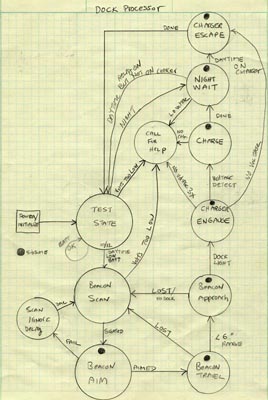 |
For
nearly ALL our docking experiments, this very carefully honed
Finite State Machine (FSM) was used. Study it carefully and you
will see that there are escape and failure contingencies to cover
nearly every situation. Making a diagram like this will enable
you to cover nearly all your bases when programming a successful
autonomous docking robot. |
Living and
working with a self charging Robot
From what we have
shown you here, you will now have a much better feel for the
possibilities and complexities of an autonomously recharging
robot. You will be opening a whole new dimension in home or office
robotics when you include this function in your creations. For
example, many people have named their Roomba floor cleaning robots
pet names, and when they finally fail, they will grieve for them
when they are gone. Your robot becomes an artificial life form
at this point it can actually sustain or "feed" itself.
We have run some of our robots for weeks on end in the house
during different projects, and after only a few days, they seem
somehow more alive as they go about their task. Our cats even
accepted P.A.A.M.I. as another animal, tried to pounce and play
with it as it roamed about.
Moving into the
Future
So where do we
go from here? With a fully autonomous self recharging robot at
hand we can start to program tasks into the machines that involve
long term goals. Examples include Daily floor sweeping, watering
the plants every two days, deliver the laundry basket to the
washer each week. And in the office, make the rounds each morning
to deliver mail, or documents. All of this is possible now, with
your self recharging robot!
|