|
|
|
|
|
|

Click on Thumbnails for large view
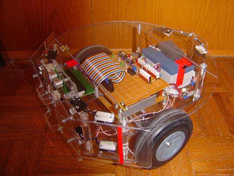
How does an autonomous robot find its battery charger, a particular point in the house, or payload drop off point? One way is with a homing beacon. Here I will detail the prototype IR homing beacon we are implementing in PAAMI for initially locating the source of power for battery charging. With this capability, the robot will be not have to be "rescued" when its battery dies, and can go to the charger and "feed" so to speak when required. In future articles we will deal with the special techniques of charging a standard Gel Cell lead acid battery as it applies to robotics.
Basic Concepts Unlike a simple cadmium sulfide light detector, a beacon detector must be able to work in a variety of lighting conditions, and use pulsed data to directly identify the beacon source from others. It must have a range that will cover most of a given room, and be directional enough to allow precise homing within an inch or better by the robot back to the source. The concept of our detector is simple: Two IR photodetectors receive a modulated signal from about half of the room, using a black opaque strip of plastic to block the other half of the room from the opposite sensor. When the two look straight ahead at the light source, a modulated IR LED, both detect the signal. When pointed either way away from the source, only one will detect the IR, since the black barrier blocks it from its view, but not the other sensors.
Accuracy depends on several factors. In our case, how close the sensors are to the black strip is one, and how long the black strip is defines the angle which both sensors consider the source to be directly ahead. In our case, at a distance of 4 feet for example, we have about a 5 degree zone in the middle where both see the source. Range can be set by the amount of current being sent to the LED's used in the source. We are using a very small amount of current, with a 330 Ohm resistor in series with the beacon LED, and get a range of about 8 feet. Any more power than this may result in reflections off walls and false sources being generated.
Mechanical Construction
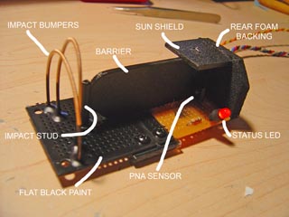
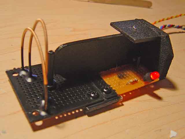
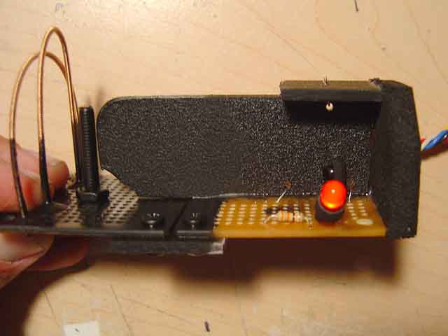
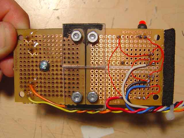
Two small perf boards are joined with a small coupler of lexan, and the black strip divider is secured in the middle with both epoxy and lashed with wire and soldered to the board underneath. The rear of the sensor array is a piece of black foam behind the IR photo detectors, and a top piece shields the array from the direct sun which can reduce its sensitivity since the IR detectors have auto gain. The sensors, Panasonic PNA4602 are three terminal devices mounted on each side of the barrier, and pressed tightly against the strip as possible. Shorter barriers made for a much larger dead zone and a 10 degree span where both sensors could see the source was unacceptable with a 2 inch strip. Our strip is 4 inches long, and an inch tall.
Two standard red LED indicators show which side is active, as well as the active low output lines to the level 6 priority subsumption processor, which will perform the navigation. Finally, Heavy brass guitar string was used (great stuff!) for a bumper sensor in front of the barrier to keep the bot from shearing off the array in an impact. The two hoops are nested such that the front one flexes to touch the rear one on impact, and making an electrical connection, detected by the overlying priority bumper sensor processor. (Ok, I tied it into the bumper switches on the front). The entire front end, including the lower half of the guitar strings - which were specular reflectors of IR I found out, were painted flat black.
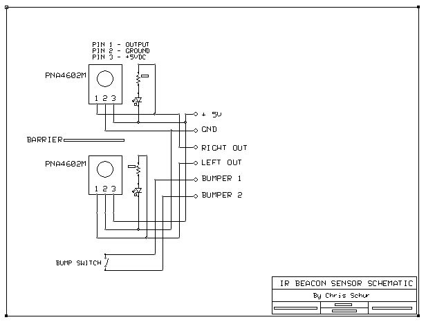
Electronics The circuit on board the beacon detector are deceptively simple. The heart is a pair of Panasonic PNA 4602M IR detectors, available from Digikey. They have some very unique characteristics that made them ideal for this application. They are better at this application, then for use in proximity detection because of the auto gain feature. As the ambient light goes down, they automatically turn up the gain internally. Which means for a proximity detector (Boe Bots use these) the distance which they become active varies from inches to several feet! Here they perform best because of the following unique characteristics:
1. They are inexpensive, simple 3 leaded devices
2. They are encapsulated in an IR filter plastic that not only sees straight ahead, but at 90 degrees just fine - no beacon will escape detection as you drive by it perpendicularly.
3. The auto gain feature is great for in home detection, as it can sense IR from many yards away
4. And most importantly, they give a TTL output level that can sink enough current to drive an LED directly when a 38.5 KHz signal is present.
What this means is you can use this device two ways. First, by simply modulating your IR LED with a continuous 38.5 KHz, a basic ON/OFF signal can be used to drive the robot toward the light. Even better, if you modulate the 38.5 KHz with a lower frequency, such as 100 Hz, you will get - you guessed it - a 100 Hz square wave out of the device. This has HUGE ramifications. By setting each beacon in the house to a different modulation frequency, say one at 100 Hz and another at 200 Hz, you can use the PIC Basic (or equivalent) "COUNT" command to determine which beacon you are looking at. So while the charging station is at the 100 Hz beacon, the floor dirt drop off can be at the 200 Hz beacon location. In theory, you can have quite a large number of beacons in a given area. In practice, its best to avoid too many in one room, so they don't make the auto gain feature saturate. Also, if BOTH beacons are detected simultaneously, the count will be neither 100 or 200 Hz and may confuse the bot. So the bottom line is careful placement of beacons will make them useful for room identification and direction markers as well. Here are some images of the beacon sensor, and a few small movies of the sensor in action.
Oblique view, without legend. Total length is about 4 inches. Side View, showing details on single sensor placement. Top View, showing the barrier clearly, both status LED's, and the top sunlight shield. Bottom View, showing wiring. Movie 1 (300K) A short clip viewed from above - showing the LED's lighting in response to rotation at two different distances. The lights are out as to show the LED's more clearly. The 38.5KHz source is connected to the blue wires on the left of the bench top. (You may have to turn your room lights down or monitor up to see this clearly) Movie 2 (300K) Full 90 degree rotation showing perpendicular detection of the PNA sensors, which will allow the robot to see the beacon even if it is not looking directly at the source. It can do this because the encapsulating housing of the sensor is solid IR filter plastic.