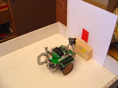
Pixy Camera Test Robot A color sensor with brains. Above: Setting an exact distance from the target for docking demonstration. Updated 6/10/17 Key Search Words: ROBOT, ROBOTICS, ROBOTIC VISION, ARTIFICIAL INTELLIGENCE, AI

The CMU-5 is a huge departure from the previous robotic vision cameras in the series, in a well balanced attempt to make some form of robotic vision more usable for the home experimenter and professional engineers alike. What this camera essentially represents is a sophisticated color sensor, which when properly set up with a PC running a small application, can detect 8 different colors and report in a data stream the size, position, and identity of patches of uniform hue. The camera has a very fast processor in it and produces a large amount of data every 50 ms. For our experiments, we set up the camera with the USB cable and PC app for what would be the most useful home application, a single color detection.
We configured the camera to put out a serial stream to the UART in the PIC, and runs quite fast at 19,200 bps. Sync to such a stream proved a bit challenging, and there were a lot of false starts. The problem was that the stream puts out two bytes of zero followed by either the actual data or no data at all. The porting guide was not clear on this, and ignoring the leading zeros was finally overcome.
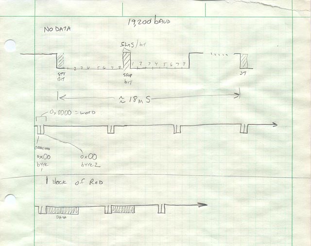
Summary of this write up: 1. Overview of the serial data stream 2. How to sync to the data 3. Lens distortion notes and compensation 4. The test setup in the Robot Arena 5. You Tube movies of the robot in action. 6. Issues with color detection in the Home environment 1. The Serial Data StreamThe serial data stream is standard 8N1 rs232, and is in packets sent every 50ms. At 19,200 baud, you can fit three "objects" within the 50ms, and then it starts over again on the next 50ms. Faster serial rates would allow more objects. But for 99% of applications, one object per frame is good enough for navigation, and localization. Three would be nice for complex 2d navigation tasks, and identifying objects in the cameras field (like plants or beacons). The part that took me the most time to assimilate was the leading two bytes of zeros at the start of every 50ms frame. This is not clearly stated in the porting guide for the camera! But you could sync the scope on this and then add a colored object into the cameras field to see what changes.
Here is a drawing I made of the waveform with NO objects in the frame on top and on the bottom, one object in the field showing the data pattern after the leading zeros:
Le 2. How to sync to the data for examination:
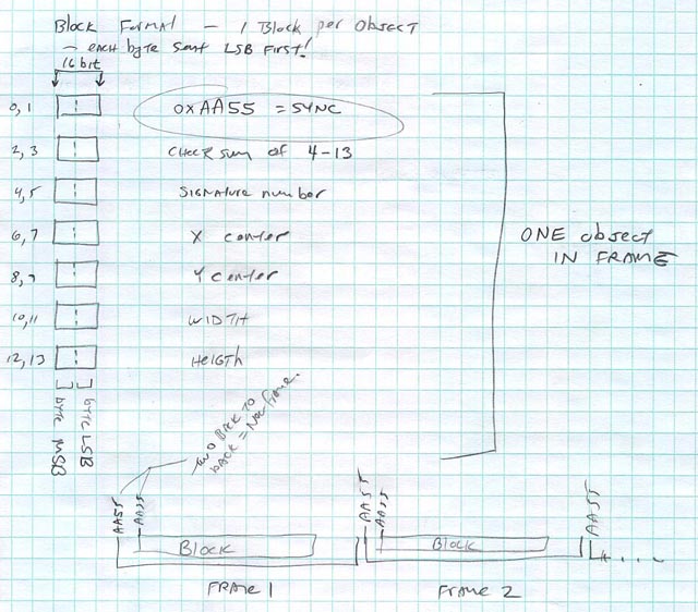
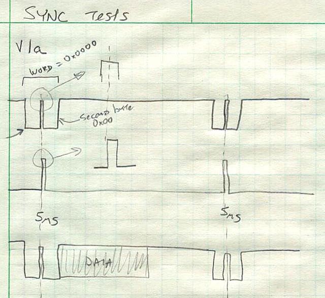
The data pattern itself is pretty easy. When block of data is coming for the entire frame, you'll get a leading 0xAA55 sync word. Then the actual data starts in sequence starting again with the 0xAA55 sync. So by looking for two syncs in a row, we identify the start of the set of data. You then download as fast as you can the next 16 bytes of data, combine to form the complete data words and save as data in a dedicated variable or perhaps as the rather poorly written example does in an array. (Try to read examples written in ANOTHER form of C code with commands you have never seen before!) For my first data sync tests for the oscilloscope, I had the processor put out a 10ns pip every time it saw two consecutive 0x00 bytes appear. This gave me a solid scope trigger. Then I put a red object in the cameras field and the data appears. With a nice solid sync, you can actually read the data bytes on the scope screen.
The data can by seen clearly by using the processor to generate a sync pulse. The bottom trace is with data on. This block is one "object"
in the cameras frame and contains the info on the object like width, height, etc. You cant sync a scope on such a waveform - you get a jumble. So thats why I started this way to learn the data pattern.
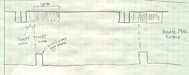
You can also sync by making the processor put out a pip when it sees the two sync words in a row. Here, the sync pip of course is located after the 0xAA55 pattern. You can then zoom in with the scope time base and actually look at the current data stream.
3. Lens distortion issues to deal with:
Sync on data using dual sync words
Example code at end of THIS page.
The cameras wide angle lens is great for seeing a nice wide field to look for objects. HOWEVER...
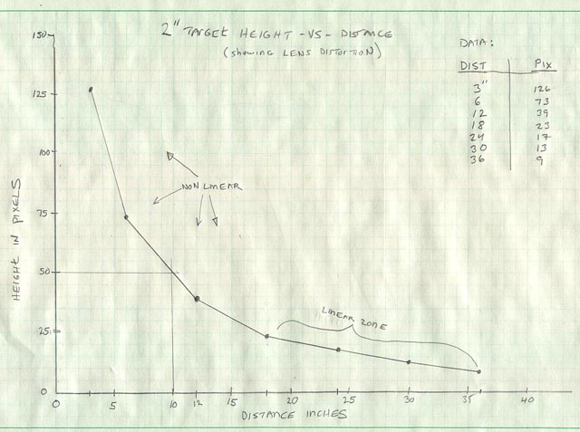
such a lens has a huge barrel distortion! What this means is if I am looking at a target of a fixed size, and back away or get closer to it, the amount that the size - either the width or height changes will not be proportional. This "non-linearity" as it is called means that if I am looking at a 2" square at a foot, then move to 6", the size of the square in pixels will not double. The lens has compression at its edges of the field, so the problem is this, when you try to measure the distance to a target for navigation, you will not get the correct number unless you make the corrections.
Left: A graph of the width of a 2" red target vs distance in inches. If it was a perfect lens, the line would be strait.
3. Setup in the Robot Arena:
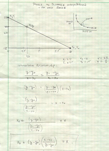
To compensate, we have to record data points for different distances, make a graph of the data. For other distances we are going to interpolate between known points to get a far more accurate distance to our target.
Here I show a typical interpolation math routine. The interpolation relationship is show just under the graph. Solving for X yields the true distance in inches between two known values.
At the bottom is the equation we will be using to get our distance. Writing this equation in C yields this formula:
X = (x0 + ((y - y0) * ((x1 - x0) / (y1 - y0))))
Ill show you the code in a bit...
I cant stress too much the importance of being able to measure the distance to a target accurately for navigation. By getting the distance for several - perhaps multi colored markers, you can triangulate your exact position in the room. Robots need to know where they are and this passive approach without the use of beacons is very handy!
Example interpolation code at bottom of this page.
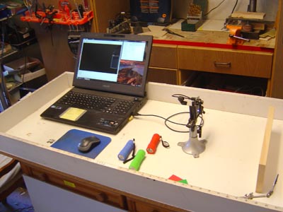
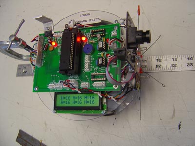
Before we connected the camera to a mobile robot, we first set up in the Arena the camera in a board vise looking at a target on a white background. This allowed us to set the camera up with the PC for one object per frame, and red as the color. Demonstrations and experiments in the Arena with the TDR robot:
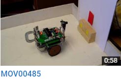
Here are a collection of videos I posted on You Tube of the trials with the camera. Each one had to have different code of course and some representative code will be shown later. For now, here are some things you can do with one object per frame detection. Turn your sound up on the computer, there is something to hear!
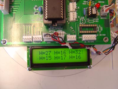
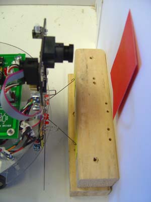
Setup for reading widths on the LCD prior to mobile robot tests:
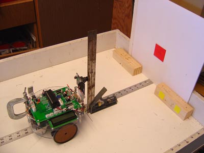
The alignment of the camera to 90 degrees is a good thing to do to ensure the lens distortions are equal in all directions on the target. The target is at the same height as the lens.
The display reads constantly the height of the target. I can push the robot back and forth and see the number change.
The distance is set with a ruler set on the floor of the arena. 1. Keeping a constant Distance. For this clip, we turn on the robot, and the program keeps the width of the target constant by moving closer or farther from it so it stays the same in the camera field:
Movie clip 1
2. rotate and set dist to moving target. Now Ive added rotation to the mix. It keeps the target centered left and right as well as the distance by not only setting the width to a fixed value, but also rotation of the robot to put the center of the target at the center of the cameras pixels (340 wide field).
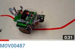
clip 23. Line Following. For this clip, we took the above program and did not change it. The camera was tilted downwards at the ground and a red line was put on the floor of the arena which - this is important - is narrower in the field than the set target distance size. The robot keeps going forward trying to set that distance (which it cant - its on the floor) and keeps centering right and left the wavy red line. Thus the robot "Line Follows" until it ends and then it sees no more line, just a white background and stops.
Clip 3
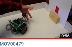
4. Simulated docking with a target. Here the robot is set to travel to a target until it is a fixed size in the field. Then it stops. This is used to direct it to a mock up of a docking station, complete with yellow contacts for its feelers to connect with to charge the robots battery up. This is normally done with active LED beacons, but here we can do it with no beacon, just vision. (nice background music too)
Clip 4
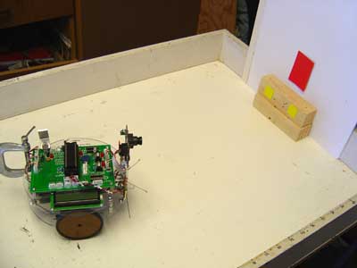
Here are some stills of this sequence which describes the action:
The robot must first rotate to get the target near the middle of its field.
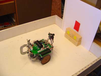
Next we drive forward, keeping it in the middle at the same time.
Inches from the target, we are almost there.
The robot stops when it has the width set - this is chosen to be when it just puts the contacts on the springy feelers in slight compression. They are now ready to charge the batteries if they were real copper contacts!
The right left precision is really good, puts the feelers on the contacts in their centers every time. 5. Touch and go docking. To prove we can accurately reach the charger over and over successfully, this program docks the robot, backs off and repeats several times with pinpoint accuracy.
Clip 5
4. Color Issues in the Home environment
To effectively work in the home, the color detection must be robust and nearly independent of lighting conditions. For this PIXY camera, this was not the case. Although it is designed to work with color hue instead of direct RGB color, even a small change after the initial white balance calibration made it not see the test color chip. An example of this was seen early on in the Arena, when I would tilt the color chip down so it was not illuminated directly by the overhead light but light bounced off the floor and in from windows. The chip was not seen at all or barely. This makes the use of this camera problematic in the home environment where lighting is always changing throughout the day, and can come from interior types of illumination or from a north facing window, which has the exact opposite color temperature as incadecent lights. Adjustments for the color hue accepted can be varied in the setup software. But by the time I got it to read a color chip illuminated by interior lights instead of an overhead fluorescent or sunlight it would see ANY color as an object!
So the bottom line here is that in a lab enviornment where we can accurately and safely control the lighting conditions, the camera works fairly well. But take it away from perfect and it fails miserably. For this reason I cannot use this device - No matter how cool it is - for a home robot. I feel the best bet for this camera as is could be perhaps in total darkness at night, and use on board LED illumination to light the field in a uniform way. (with that wide angle lens, that is a TALL order!). Beyond that, which is impractical when we really need the robot to do its work, its not acceptable in terms of reliability. The CMU 5 is a wonderful technological achievement - but its not quite there yet.
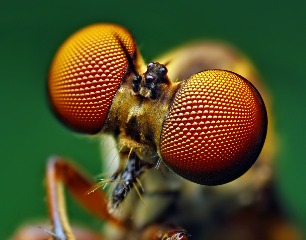
Finally, I will continue to pursue and test other methods of vision in robotics. If insects with their pin point brains can do it, so can we. Im guessing that sticking with black and white cameras for now will be a safer bet.
Code Section. Ive put this listing at the very end to keep this page organized and readable. The robots program is large and complex, so Ill only post the C code for two parts - Data acquisition from the serial stream, and the Interpolation routine.
1. Getting data from the camera requires 4 nested loops, including the main program loop. This is necessary because the data in non synchronous.
-----------------------------------------------------------------------------------------------------------------------------------
Main program loop:
//Main Program
while(true) {
GETCAMDATA();
if(FLAG == 1) { //we have good data
output_high LED;
output_low GREEN;
}
if(FLAG == 0) { //no data found
output_low LED;
output_high GREEN;
}fprintf(SERIALNH,"H=%Lu ",HEIGHT);
} //while
//********* Functions which have prototypes at top of program ****************
//PIXY:
int16 getword(void) { //gets the data and makes it into a 16bit word.
int16 w;
int8 c;
c=fgetc(PIXY);
w=fgetc(PIXY);
w <<= 8;
w |= c;
return w;
}
void GETCAMDATA(void) { //Looks for double sync or double zeros
while(true) {
CURR = GETTYPE();if(PREV && CURR) { //Two Sync words in a row found - Quick GRAB DATA
CHECKSUM = getword();
SIGNATURE = getword();
XCENTER = getword();
YCENTER = getword();
WIDTH = getword();
HEIGHT = getword();
FLAG = 1;
break;
}
if((PREV == 0) && (CURR == 0)) { //Two zero data words found - NOTHING FOUND
SIGNATURE = 0;
XCENTER = 0;
YCENTER = 0;
WIDTH = 0;
HEIGHT = 0;
FLAG = 0;
break;
}PREV = CURR; //if prev and current not same, do this keep looping.
} //while
return;}
//----------------------------------------------------------------------
int GETTYPE(void) {
while (true) {
//get one word:
SERDATA = getword();
if((SERDATA == 0) && (PREVSERDATA == 0))
return 0;
else if ((SERDATA == 0xaa55) && (PREVSERDATA == 0xaa55))
return 1;PREVSERDATA = SERDATA; //Save old data
} //while - Keep looping until you find one of the two types of data
} //GETTYPE
--------------------------------------------------------------------------------------------------------------------------
Code for interpolating distances from cam data width.
Prototype at top of program:
float32 INTERPOLATE(float32 X1,float32 Y1,float32 X0, float32 Y0,float32 Y);
Main Loop:
//Main Program
while(true) {
//inputs will be X1,Y1,X0,Y0,Y and output X. (distance in inches)
//xaxis is distance, y axis is number of pixels wide.Xi = INTERPOLATE(4,25,6,15,22);
LCDCLR();
delay_ms(25);
fprintf(SERIALNH,"Xi= %f ",Xi);delay_ms(250);
} //while
//********* Functions which have prototypes at top of program ****************
float32 INTERPOLATE(float32 X1,float32 Y1,float32 X0, float32 Y0,float32 Y) {
float32 X;
X = (X0 + ((Y - Y0) * ((X1 - X0) / (Y1 - Y0))));
return X;
}
//-------------------------- end ------------------------------------------------------------------------------------
Previous Uploads on this robot:

NONE.