NavBot 3-A "Arm Logic Robot" Updated 6/26/14 
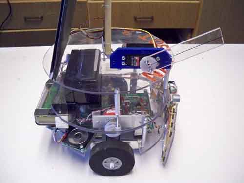
Left: Lets start with the configuration of the test robot. The general purpose robot developed in the NavBot series is being used because it has correct small size, and features to perform the Arm Logic project. The robot consists of three tiers, the bottom tier is the motor drive, primary sensors and the home brew professional grade PCB we made which contains a powerful PIC Micro controller, the 16F877a. Driven by precision DC gear motors, this bot also has a Devantech text to speech processor (the robot can talk), a frontal sonar and bumper array, and optical shaft encoders on the right wheel for distance.
The mid deck contains the LCD display, 12v gel cell battery and will carry any supplemental electronics for the arm.
The top deck has a central non-ferrous mast with a digital compass on top, and a large solar panel for robot charging in the sun. The arm will be built on the top section.
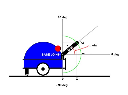
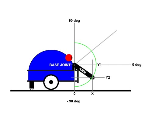
Left: Lets start by projecting a simple polar coordinate system on to the robots front section, with the arm pivot that is motor driven at the origin (0,0) location. When the arm moves it sweeps a radius on its end from straight up, to a point near the ground, but not quite straight down due to mechanical considerations.
Put simply, the end of the arm can be defined by three equations:
X = r(cos theta) for top quadrant: Y = r(sin theta) + h for bottom quadrant: y = h - r(sin theta) Where "h" is the height of the base of the robot arm off the floor.
For example, if the arm is straight up, X=0, Y=r and because the arm of the robot is 4 inches long from hole to hole, the arm is 4 inches up over the motor.
For an angle of 45 degrees down as seen here, X = r (cos 45)
= 4" (.71) = 2.8"
and for Y:
Y= h - r(sin theta)
Y = 7.5" - 4" (.71) = 7.5 - 2.8 = 4.7"
since h is 7.5" for our robot.
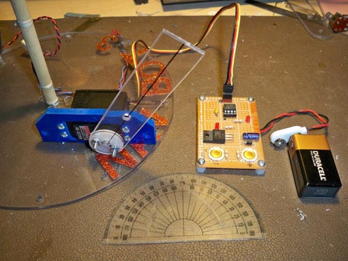
Left: Set up for measuring the pulse width vs angle. A PIC micro generates the 1 - 2 ms pulses for the servo and can be ramped up and down with the push buttons. This is for test only! The real robot would be able to actually move the arm by itself with its own micro. For those interested in which processor I used, I am quite fond of the 12F629 chips, they can be had for under a dollar, and with their small 8 pin dip package, are simple to use.
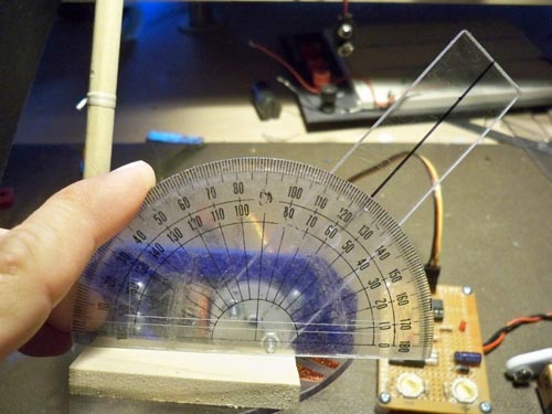
Left: By setting the servo to put the arm at various angles, we can measure the pulse width and check linearity to generate an equation for the transform. Here for example we have the arm set for 45 degrees.
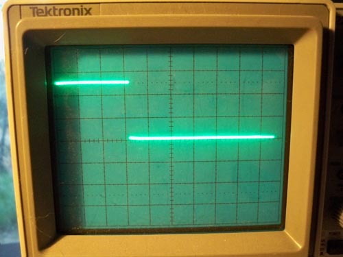
Left: O-Scope shot of the pulse out of the micro, showing here a pulse 1.6 ms wide. The spacing is always 20 ms or so.
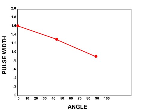
Left: Graphing the results. It is fairly linear, and we can use this information to generate an empirical formula for the angle vs the pulse input for our robot!
First we calculate the change in pulse width per degree:
.8 ms change / 90 degr change = .0088 ms/deg
For a 45 degree angle we then know:
.0088 x 45d = .4ms. Subtract this from our zero point of 1.6ms and we get 1.6-.4 = 1.2ms. This is the pulse width to set the angle to 45 degrees.
Practical applications of a one arm segment robot
There are of course limits to what you can do with a robot arm consisting of one movable section. You might be surprised however on what can be done compared to a robot with NO arm at all. For example, you have no doubt seen robot simulations where a robot with no arm seems to be able to magically "push" a puck to various locations in the test arena with no problem. This is not real world. In a home environment, the robot would not be able to keep the puck centered to push it for any distance, and irregularities on the floor will make it go off course or stop it in no time at all. You must reach out, grab the item of interest and Lift it off the floor to be able to successfully move it around. This is where an arm comes into play. Even a simple magnet or gripper on the end of a arm segment can grasp the object, and lift it off the ground. Then the robot can either stow the object or lift it out of the way of the frontal sensors and travel to its next destination with its payload. Lets explore how this might occur.
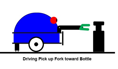
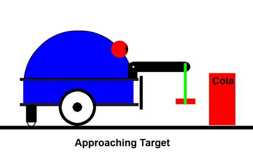
Left: Here is an example of a type of end effector that is fixed and unjointed with a large number of home uses. A simple stationary fork on the end of the arm bar can be directed to essentially scoop up packages which have a specific narrow shape on the top. It is common in the robotics industry to use robots to carry cargo that is placed in "Robot transport containers" so they can be easily grasped. An example of this is the fork used to lift your trash can dumpster by the robotic arm on the garbage truck and lift it to empty it.
Left: Step two of this procedure is to insert the fork around the narrow top, and lift it off the floor. We do not want the cargo to drag or have to push it toward its destination! (not good for the wooden floors in the house either)
Once it is lifted, we can either proceed to the destination, but with hampered frontal sensors. If we are line following this wont be a problem as long as we dont hit someone or an obstacle in the path. The robot will not be able to sense the obstacle and we could have a problem there.
Left: Now lifted into the final transport position, up high and allowing the bumpers and sonar to work properly to navigate to the delivery point. (like water plants, deliver the paper, etc.)
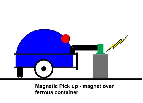
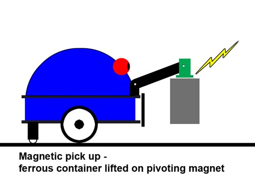
Left: Now here is another method to lift and transport with a one segment arm. By putting an electro magnet on the end of the bar, we can move ferrous containers and items about with a good firm grip without the use of additional grippers. Here the container is being touched on the top with the arm.
Left: Next we lift the container off the floor for transport. Note the magnet is on a hinge so that it does not tilt off the surface and loose its grip. Depending on the weight of the container, you may or may not be able to lift it fully to the upright stowed position for sensor usage when moving.
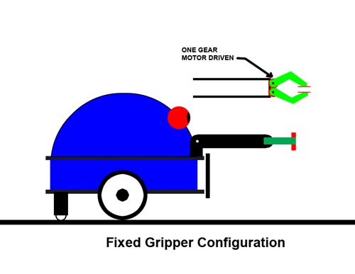
Left: A straight on gripper can be constructed to grab a variety of objects at various angles. If the arm is tilted down, it can grab lower objects than seen here. This setup is the typical dual gear drive type, where one gear is motor driven by a small servo and the meshed gears move both claws by the same amount.
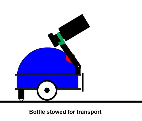
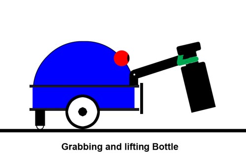
Left: This is the configuration I have used for item transport in past robots. The gripper is the same as the above type, but is rotated 90 degrees to angle down. To grip something, you basically open the jaws, lower the boom and close the downward pointing grippers. This makes it easy to reach objects on the floor that are low, or wide.
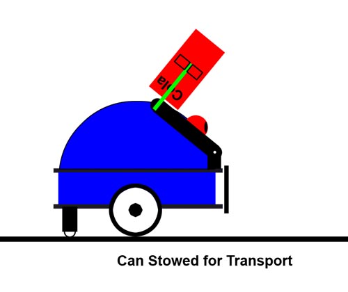
Left: Now the can is in the stowed position using this setup. Full use of the frontal sensors is available now, and you can safely navigate to the goal.
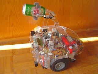
Below - Paami using this type of grasping arrangement:
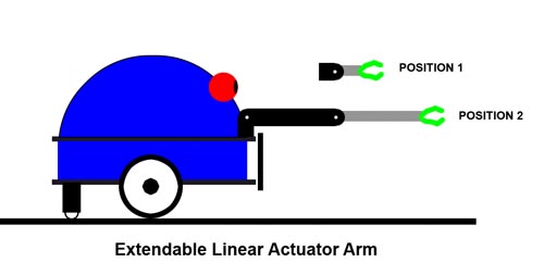
Left: One additional type I should mention is the use of "Linear Actuators" to extend the reach of the arm. This can be used to a great advantage and increases the radius of grasp around the front of the robot. Linear actuators are somewhat expensive, but can be home built as well with a small motor and rack and pinion arrangement.
This finishes our basic overview of one arm operation. There can be many variations on this theme, here I just intend to get you started on thinking about the wide range of uses for a simple one segment arm can generate. Next, we will put some of these ideas to the test, and demonstrate in hardware these concepts for real!