Adafruit Triple axis Compass Chip

Updated 9/21/15

Key Search Words: PIC Microcontroller, CCS C Compiler, PIC Projects

 This project was a spin off from the use of the Adafruit 3 axis magnetometer navigation element in our current robot, the plant watering robot. The Adafruit magnetometer is an amazing sensor, built on a tiny break out board complete with TTL level conversion and direct I2C interface to your microcontroller. The best part? its only $9. I bought two of them and while one went into C-Bot, the other is included as the primary sensor in this project. This project takes the compass data, and sends it serially over the RS232 TX line using the UART at 9600kb as two bytes which represent the 0 - 360 degree data x 100. Then on the receive side, your main micro controller takes the data and divides by 100 to get the full 0 - 360 with two decimals.

The purpose of all of this was to offload the huge 3k of compass driver from the main processor and allow it to have much more program space, and not have to deal with this complex driver code with its two big math libraries. Shown here is the actual compass chip, followed by a typical main processor, the 16F887 receiving the data.

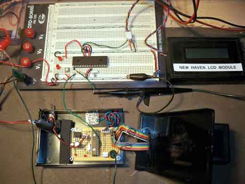
Left: Bench setup with compass chip (PIC16F876a) in a housing with the Adafruit compass board at the top of the box, just above the compass processor. The top large processor is the receive chip, and is a PIC16F887 which sends it data to the LCD on the right.
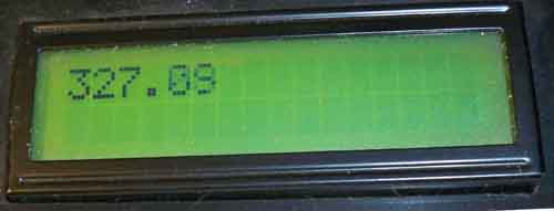
Showing the received data in degrees as received from the main processor.
Schematic for the compass chip - Click to Enlarge.
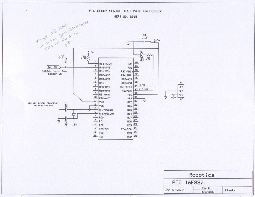
Schematic for the 887 receive chip - click to enlarge.
CCS-C code for the Compass Chip:

 //****************************************************************************
//Chris Schur
//(Compass Sensor Chip - 1 16F876a)
//Date: 9/14/15
//****************************************************************************

/*Description of this Program:

This version - Sends 5 digits serially of compass data from the Adafruit compass module

*/


//I/O Designations ---------------------------------------------------
// RA0:
// RA1:
// RA2:
// RA3:
// RA4: (Open Collector output)
// RA5:

// RB0:
// RB1:
// RB2:
// RB3:
// RB4:
// RB5:
// RB6:
// RB7:

// RC0: Status LED output
// RC1: LCD output
// RC2:
// RC3: INPUT - SCL - to magnetometer
// RC4: INPUT - SDA - to magnetometer
// RC5:
// RC6: serial TX UART
// RC7:


//--------------------------------------------------------------------

//Include Files:
#include <16F876A.h> //Normally chip, math, etc. used is here.
#include "math.h" //required for compass

//Directives and Defines:

#fuses NOPROTECT,HS,NOWDT //xtal is used
#use delay(crystal=10MHz) //xtal speed

//set up i2c - data, clock pins are here hardware on 877a.part uses slow spec.
#use I2C(master, sda=PIN_C4, scl=PIN_C3, slow, FORCE_HW) //HARDWARE IMPLEMENT


#use fast_io(ALL) //must define tris below in main when using this

// HMC5883 required Registers
#define W_DATA 0x3C //Used to perform a Write operation
#define R_DATA 0x3D //Used to perform a Read operation
#define CON_A 0x00 //Sets up measurement and sampling parameters.
#define CON_B 0x01 //Send continuous MeVARurement mode.
#define MOD_R 0x02 //Read/Write Register, Selects the operating mode. Default = Single meVARurement
#define X_MSB 0x03 //Read Register, Output of X MSB 8-bit value.
#define X_LSB 0x04 //Read Register, Output of X LSB 8-bit value.
#define Z_MSB 0x05 //Read Register, Output of Z MSB 8-bit value.
#define Z_LSB 0x06 //Read Register, Output of Z LSB 8-bit value.
#define Y_MSB 0x07 //Read Register, Output of Y MSB 8-bit value.
#define Y_LSB 0x08 //Read Register, Output of Y LSB 8-bit value.

//for LCD:
#use rs232(baud=9600, xmit=Pin_C1, bits=8, parity=N,stream=SERIALNH)
//for data out to main processor:
#use rs232(baud=9600, xmit=Pin_C6, bits=8, parity=N,STREAM=COMPASS)


//****************************************************************************
//Global Variables:
int8 M_data[6]; //Array - 6 units 8 bit Measured datas (compass)
int16 Xm=0,Ym=0,Zm=0; //16 bit X,Y,Z variables (compass)
float bearing; //final compass reading.
int16 bearing2; //compass bearing x 100, no decimal
int highbyte,lowbyte; //high byte and low byte for serial data

//****************************************************************************


//Functions/Subroutines, Prototypes:

//for compass only:
void hmc5883_write(int add, int data); //write to function
int16 hmc5883_read(int add); //Read from function
void hmc5883_init(); //Sets up starting conditions
void read_reg(); //reads compass registers, calc xyz
float calc_heading(); //calculates returns bearing.


//Clears LCD Display:
void LCDCLR() {
fputc(0xFE,SERIALNH); //Command Prefix
fputc(0x51,SERIALNH); //Clear screen
}

//Sets LCD to line 2 start point
void LCDLN2() {
fputc(0xFE,SERIALNH); //Command Prefix
fputc(0x45,SERIALNH); //set cursor command
fputc(0x40,SERIALNH); //Set cursor to next line, pos 40 = start line 2
}


//****************************************************************************
//-- Main Program
//****************************************************************************

void main(void) {

// Set TRIS I/O directions, define analog inputs, compartors:
set_tris_A(0b10000);
set_tris_B(0b00000000);
set_tris_C(0b00011000);


//(analog inputs digital by default)

//Initialize variables and Outputs: --------------------------------------
output_low(Pin_C0); //status off

delay_ms(1000); //LCD warmup time
//SET BRIGHTNESS OF LCD TO MID RANGE. (DEFAULT = 1)
fputc(0xFE,SERIALNH); //Command Prefix
fputc(0x53,SERIALNH); //set cursor command
fputc(8,SERIALNH); //4 is mid 0-8

delay_ms(25);

LCDCLR();
delay_ms(25);

fprintf(SERIALNH,"AUTO COMPASS-1");
delay_ms(250);

LCDLN2();
fprintf(SERIALNH,"READY");
delay_ms(1000);


//Setup for timers, PWM, and other peripherals:

//----------------------------------------------------------------

//MAIN:

hmc5883_init(); //Initialize compass settings.

while (true) {

read_reg(); //read compass registers, calc xyz

bearing = calc_heading(); //calculates & returns final compass bearing

bearing2 = (int16)(bearing * 100); //mult by 100, redefine type to int16
// so we can send it serially as two bytes. Yeilds 0 - 35999

//Convert to two 8 bit integers to send:
lowbyte = MAKE8(bearing2,0);
highbyte = MAKE8(bearing2,1);

//send data serially:
fputc(lowbyte,COMPASS);
fputc(highbyte,COMPASS);

delay_ms(10);

LCDCLR();
delay_ms(10);
fprintf(SERIALNH,"H= %Lu ",bearing2);
delay_ms(25);


} //elihw

} //naim

//********* Functions which have prototypes at top of program ****************


//for compass only:
void hmc5883_write(int add, int data) {
i2c_start();
i2c_write(W_DATA); //0x03
i2c_write(add);
i2c_write(data);
i2c_stop(); }

int16 hmc5883_read(int add) {
int retval;
i2c_start();
i2c_write(W_DATA); //0x03
i2c_write(add);
i2c_start();
i2c_write(R_DATA); //0x3D
retval=i2c_read(0);
i2c_stop();
return retval; }

void hmc5883_init() {
hmc5883_write(MOD_R, 0x00); //0x02, 0x00
delay_ms(100);
hmc5883_write(CON_A, 0x10); //0x00, 0x10
delay_ms(100);
hmc5883_write(CON_B, 0x20); //0x01, 0x20
delay_ms(100); }

void read_reg() { //read compass registers
//read registers in compass
M_data[0]=hmc5883_read(0x04); //Read X (LSB)
M_data[1]=hmc5883_read(0x03); //Read X (MSB)
M_data[2]=hmc5883_read(0x08); //Read Y (LSB)
M_data[3]=hmc5883_read(0x07); //Read Y (MSB)
M_data[4]=hmc5883_read(0x06); //Read Z (LSB)
M_data[5]=hmc5883_read(0x05); //Read Z (MSB)

//Create Word from Highbyte and Lowbyte data:
Xm=make16(M_data[1],M_data[0]);
Ym=make16(M_data[3],M_data[2]);
Zm=make16(M_data[5],M_data[4]);

}

float calc_heading() {
//Calculate using math.h function the bearing.
float Heading = atan2((signed int16)Ym,(signed int16)Xm)* 180 / pi + 180;

//correct for this equation yielding values 180 off:
if (Heading < 180)
Heading = Heading + 180;
else if (Heading > 180)
Heading = Heading - 180;
else if (Heading == 180)
Heading = 0;

return Heading;

}

CCS-C code for the Recieve Chip:

 //****************************************************************************
//Chris Schur
//(COMPASS RECV 16F887)
//Date: 9/20/15
//****************************************************************************

/*Description of this Program:

This version - receivs serial compass data at 9600kb with updates around once every 68ms*/


//I/O Designations ---------------------------------------------------
// RA0: (AN0) Compass serial data input (TIE HIGH WITH 4.7K)
// RA1: (AN1)
// RA2: (AN2)
// RA3: (AN3)
// RA4: (Open Collector output)
// RA5: (AN4)
// RA6: OSC OUT
// RA7: OSC IN

// RB0: (AN12,EXT INT) Status LED output
// RB1: (AN10) LCD output
// RB2: (AN8)
// RB3: (AN9)
// RB4: (AN11)
// RB5: (AN13)
// RB6:
// RB7:

// RC0:
// RC1:
// RC2:
// RC3: (SCLK)
// RC4: (SDA)
// RC5:
// RC6:
// RC7:

// RD0:
// RD1:
// RD2:
// RD3:
// RD4:
// RD5:
// RD6:
// RD7:

// RE0: (AN5)
// RE1: (AN6)
// RE2: (AN7)
// RE3: (MCLR INPUT - Pull High)

//--------------------------------------------------------------------

//Include Files:
#include <16F887.h> //Normally chip, math, etc. used is here.

//Directives and Defines:

#fuses NOPROTECT,HS,NOWDT //xtal is used
#use delay(crystal=10MHz) //xtal speed
#use fast_io(ALL) //must define tris below in main when using this

//for LCD:
#use rs232(baud=9600, xmit=Pin_B1, bits=8, parity=N,stream=SERIALNH)

//For reciving compass data on pin A0:
#use rs232(baud=9600, rcv=Pin_A0, bits=8,parity=N, DISABLE_INTS,stream=COMPASS)
//Note: the "disable_ints is critical, turns off constant barrage of interrupts
//during the aquisition of data in the get command so timing is not affected.

//NO_ANALOGS is default in device file...(All I/Os are digital)


//***Global Variables:********************************************************
float bearing; //final compass reading.
int16 bearing2; //compass bearing x 100, no decimal
int highbyte,lowbyte; //high byte and low byte for serial data
int16 compasstimeout; //counts of kbit delay increrments

//***Functions/Subroutines, Prototypes:***************************************
//Clears LCD Display:
void LCDCLR() {
fputc(0xFE,SERIALNH); //Command Prefix
fputc(0x51,SERIALNH); //Clear screen
}

//Sets LCD to line 2 start point
void LCDLN2() {
fputc(0xFE,SERIALNH); //Command Prefix
fputc(0x45,SERIALNH); //set cursor command
fputc(0x40,SERIALNH); //Set cursor to next line, pos 40 = start line 2
}

void GETCOMPASS(void); //this function gets the raw compass value and converts
//to floating with 2 decimals.disconnnection of serial data does not lock up
//main processor.


//****************************************************************************
//***-- Main Program*********************************************************

void main(void) {

// Set TRIS I/O directions, define analog inputs, compartors:
set_tris_A(0b10111111);
set_tris_B(0b11111100);
set_tris_C(0b11111111);
set_tris_D(0b11111111);
set_tris_E(0b1111);

//Initialize variables and Outputs: --------------------------------------


//Setup for timers, PWM, and other peripherals:

//----------------------------------------------------------------


//Main Program


while (true) {

GETCOMPASS(); //go get compass data serially

LCDCLR(); //clear screen
delay_ms(10);
fprintf(SERIALNH,"%f"bearing); //NOTE: %Lu in command is int16 only output
delay_ms(10);

//flash led
output_high(Pin_B0);
delay_ms(2);
output_low(Pin_B0);

} //while

} //main

//********* Functions which have prototypes at top of program ****************

void GETCOMPASS(void) {
//test loop to see if data has come in lasting maximum of 1/2 second:

compasstimeout = 0; //reset timeout

while (!kbhit(COMPASS) && (++compasstimeout < 50000)) //half second wait IF NO SIGNAL
delay_us(10);

if (kbhit(COMPASS)) { //We have a signal
lowbyte = fgetc(COMPASS);
highbyte = fgetc(COMPASS);
bearing2 = MAKE16(highbyte,lowbyte); //RAW
bearing = (float) bearing2 / 100; //degrees with 2 decimals
}
}

 
HOME