
This project was a spin off from the use of the Adafruit 3 axis magnetometer navigation element in our current robot, the plant watering robot. The Adafruit magnetometer is an amazing sensor, built on a tiny break out board complete with TTL level conversion and direct I2C interface to your microcontroller. The best part? its only $9. I bought two of them and while one went into C-Bot, the other is included as the primary sensor in this project.
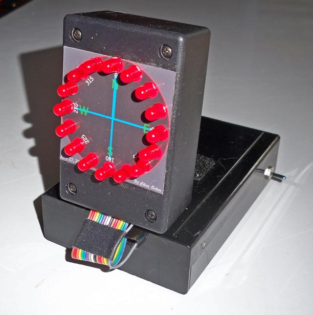
The goal here was to produce a dash mounted compass, with a bright daylight readable LED readout. The navigation of car on city streets is primarily to answer the question - which way am I going and do I turn right or left to go say west on 16th street. No need for super accuracy, just a quick view of the approximate direction your heading in both cloudy days with no guiding sun or at night. It works fantastic, and it is fun to drive around watching it change constantly!
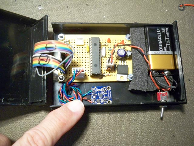
The main electronics are mounted in a flat box which contains the processor, battery and sensor. No metal parts near the sensor of course! A two position display was hand made using a color inkjet print that was designed in Autocad, colored in Photoshop, and laminated. The display box with 16 LEDs can be mounted both horizontal for hand held use or at 90 degrees for automotive as seen in these photos. I have still quite a few PIC16F876a chips laying around, and I used one of these powerful devices for the master processor. Code was written in CCS-C and takes up about half the ROM. (about 2k words). So without delay, here is the photo details of this fun project:
Below: Front view in automotive display mode.
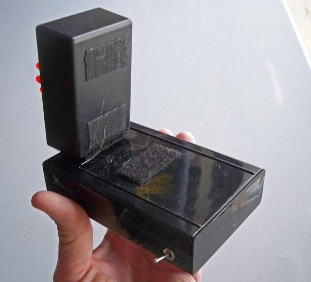
Below: Rear view showing the velcro allowing it to be either stood up or lay flat.
Below: Inside the main box - the sensor is the small blue board I am pointing at. What a magnificent device!
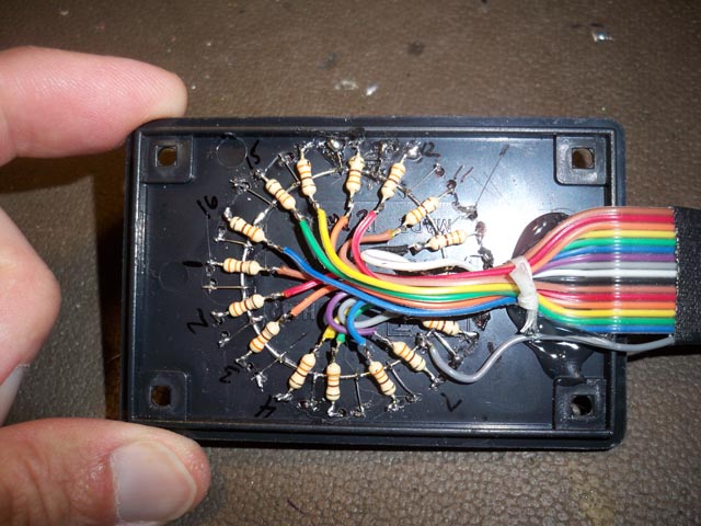
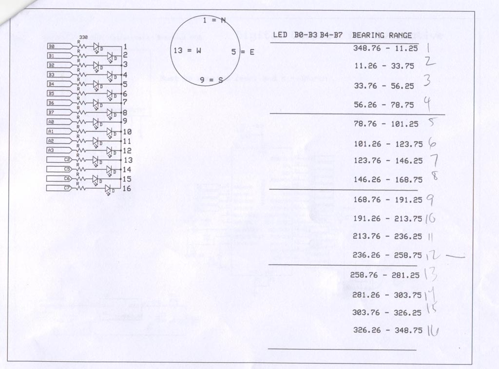
Below: The HARDEST part to build was this display. Each LED has its own 330 ohm resistor and a ribbon cable connection.
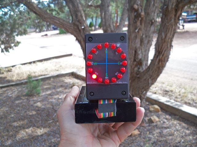
Below: Compass outdoors in action - lookkin South West.
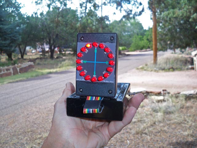
Below: Another "action" shot. Here looking down the street almost north.
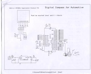
Below: Schematic page 1 & 2- CLICK TO ENLARGE
Below: C code for this project.
//****************************************************************************
//Chris Schur
//(Auto Compass1 16F876a)
//Date: 7/2/15
//****************************************************************************/*Description of this Program:
This program reads the Adafruit Magnetometer, then bins the bearings into
16 ranges. Then lights one of the 16 LEDs on the circular ring diplay.version 5 - final version */
//I/O Designations ---------------------------------------------------
// RA0: LED9
// RA1: LED10
// RA2: LED11
// RA3: LED12
// RA4: (Open Collector output)
// RA5:// RB0: LED1
// RB1: LED2
// RB2: LED3
// RB3: LED4
// RB4: LED5
// RB5: LED6
// RB6: LED7
// RB7: LED8// RC0: Status LED output
// RC1:
// RC2: LED13
// RC3: INPUT - SCL - to magnetometer
// RC4: INPUT - SDA - to magnetometer
// RC5: LED14
// RC6: LED15
// RC7: LED16
//--------------------------------------------------------------------
//Include Files:
#include <16F876A.h> //Normally chip, math, etc. used is here.
#include "math.h" //required for compass//Directives and Defines:
#fuses NOPROTECT,HS,NOWDT //xtal is used
#use delay(crystal=10MHz) //xtal speed//set up i2c - data, clock pins are here hardware on 877a.part uses slow spec.
#use I2C(master, sda=PIN_C4, scl=PIN_C3, slow, FORCE_HW) //HARDWARE IMPLEMENT
#use fast_io(ALL) //must define tris below in main when using this
// HMC5883 required Registers
#define W_DATA 0x3C //Used to perform a Write operation
#define R_DATA 0x3D //Used to perform a Read operation
#define CON_A 0x00 //Sets up measurement and sampling parameters.
#define CON_B 0x01 //Send continuous MeVARurement mode.
#define MOD_R 0x02 //Read/Write Register, Selects the operating mode. Default = Single meVARurement
#define X_MSB 0x03 //Read Register, Output of X MSB 8-bit value.
#define X_LSB 0x04 //Read Register, Output of X LSB 8-bit value.
#define Z_MSB 0x05 //Read Register, Output of Z MSB 8-bit value.
#define Z_LSB 0x06 //Read Register, Output of Z LSB 8-bit value.
#define Y_MSB 0x07 //Read Register, Output of Y MSB 8-bit value.
#define Y_LSB 0x08 //Read Register, Output of Y LSB 8-bit value.
//defining the LEDs
#define LED1 Pin_B0
#define LED2 Pin_B1
#define LED3 Pin_B2
#define LED4 Pin_B3
#define LED5 Pin_B4
#define LED6 Pin_B5
#define LED7 Pin_B6
#define LED8 Pin_B7
#define LED9 Pin_A0
#define LED10 Pin_A1
#define LED11 Pin_A2
#define LED12 Pin_A3
#define LED13 Pin_C2
#define LED14 Pin_C5
#define LED15 Pin_C6
#define LED16 Pin_C7//****************************************************************************
//Global Variables:
int8 M_data[6]; //Array - 6 units 8 bit Measured datas (compass)
int16 Xm=0,Ym=0,Zm=0; //16 bit X,Y,Z variables (compass)
float bearing; //final compass reading.//****************************************************************************
//Functions/Subroutines, Prototypes:void LEDZERO(void); //zeros all 16 outputs
//for compass only:
void hmc5883_write(int add, int data); //write to function
int16 hmc5883_read(int add); //Read from function
void hmc5883_init(); //Sets up starting conditions
void read_reg(); //reads compass registers, calc xyz
float calc_heading(); //calculates returns bearing.//****************************************************************************
//-- Main Program
//****************************************************************************void main(void) {
// Set TRIS I/O directions, define analog inputs, compartors:
set_tris_A(0b10000);
set_tris_B(0b00000000);
set_tris_C(0b00011000);
//Initialize variables and Outputs: --------------------------------------
output_low(Pin_C0); //status off
//now set all the LEDs on the display module to off.
LEDZERO(); //TURN OFF LEDS
//----------------------------------------------------------------//MAIN:
hmc5883_init(); //Initialize compass settings.
while (true) {
read_reg(); //read compass registers, calc xyz
bearing = calc_heading(); //calculates & returns final compass bearing
//Next we light the correct LED according to the value.
if (bearing >= 348.8 || bearing < 11.3) {
LEDZERO();
output_high(LED1); }
else if (bearing >= 11.3 && bearing < 33.8) {
LEDZERO();
output_high(LED2); }
else if (bearing >= 33.8 && bearing < 56.3) {
LEDZERO();
output_high(LED3); }
else if (bearing >= 56.3 && bearing < 78.8) {
LEDZERO();
output_high(LED4); }
else if (bearing >= 78.8 && bearing < 101.3) {
LEDZERO();
output_high(LED5); }
else if (bearing >= 101.3 && bearing < 123.8) {
LEDZERO();
output_high(LED6); }
else if (bearing >= 123.8 && bearing < 146.3) {
LEDZERO();
output_high(LED7); }
else if (bearing >= 146.3 && bearing < 168.8) {
LEDZERO();
output_high(LED8); }
else if (bearing >= 168.8 && bearing < 191.3) {
LEDZERO();
output_high(LED9); }
else if (bearing >= 191.3 && bearing < 213.8) {
LEDZERO();
output_high(LED10); }
else if (bearing >= 213.8 && bearing < 236.3) {
LEDZERO();
output_high(LED11); }
else if (bearing >= 236.3 && bearing < 258.8) {
LEDZERO();
output_high(LED12); }
else if (bearing >= 258.8 && bearing < 281.3) {
LEDZERO();
output_high(LED13); }
else if (bearing >= 281.3 && bearing < 303.8) {
LEDZERO();
output_high(LED14); }
else if (bearing >= 303.8 && bearing < 326.3) {
LEDZERO();
output_high(LED15); }
else if (bearing >= 326.3 && bearing < 348.8) {
LEDZERO();
output_high(LED16); }
} //elihw
} //naim//********* Functions which have prototypes at top of program ****************
void LEDZERO(void) { //this function sets all LED outputs to 0.
output_B(0b00000000);
output_low(LED9);
output_low(LED10);
output_low(LED11);
output_low(LED12);
output_low(LED13);
output_low(LED14);
output_low(LED15);
output_low(LED16); }
//for compass only:
void hmc5883_write(int add, int data) {
i2c_start();
i2c_write(W_DATA); //0x03
i2c_write(add);
i2c_write(data);
i2c_stop(); }
int16 hmc5883_read(int add) {
int retval;
i2c_start();
i2c_write(W_DATA); //0x03
i2c_write(add);
i2c_start();
i2c_write(R_DATA); //0x3D
retval=i2c_read(0);
i2c_stop();
return retval; }
void hmc5883_init() {
hmc5883_write(MOD_R, 0x00); //0x02, 0x00
delay_ms(100);
hmc5883_write(CON_A, 0x10); //0x00, 0x10
delay_ms(100);
hmc5883_write(CON_B, 0x20); //0x01, 0x20
delay_ms(100); }
void read_reg() { //read compass registers
//read registers in compass
M_data[0]=hmc5883_read(0x04); //Read X (LSB)
M_data[1]=hmc5883_read(0x03); //Read X (MSB)
M_data[2]=hmc5883_read(0x08); //Read Y (LSB)
M_data[3]=hmc5883_read(0x07); //Read Y (MSB)
M_data[4]=hmc5883_read(0x06); //Read Z (LSB)
M_data[5]=hmc5883_read(0x05); //Read Z (MSB)
//Create Word from Highbyte and Lowbyte data:
Xm=make16(M_data[1],M_data[0]);
Ym=make16(M_data[3],M_data[2]);
Zm=make16(M_data[5],M_data[4]);
}float calc_heading() {
//Calculate using math.h function the bearing.
float Heading = atan2((signed int16)Ym,(signed int16)Xm)* 180 / pi + 180;
//correct for this equation yielding values 180 off:
if (Heading < 180)
Heading = Heading + 180;
else if (Heading > 180)
Heading = Heading - 180;
else if (Heading == 180)
Heading = 0;
return Heading;}