
Thermistor based indoor
temperature indicator for the
Security Web Cam

This project was inspired by the desire to know the daytime temperature in our home upstairs during the hot parts of the day usually while we were at work or away on weekends. This can be critical for pets, plants and other home items that are temperature sensitive. Recently, I re-discovered an old Radio Shack temperature sensitive resistor in my storage drawers and it then became a project to learn more about these devices and develop the skills needed in programming to make a useful project that was beneficial to the house.
The result is here, a microcontroller based monitoring system which reads the thermistors output, applies the appropriate calibration equations and tables and then displays the reading, accurate to 1 degree on both an LCD display and a flashing big LED which can be seen on any of the numerous security web cams we have in our home and then read remotely. The final project works very well, and gave me a good understanding of both the thermistor and how our web cams sample images!
Below I will illustrate the final device, schematics, a movie of it in action, all the math, and then the C code.
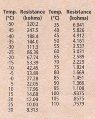
This is the chart on the back of the package that held the original thermistor part. You can see it has quite a temperature range. I was primarily interested in -30C to about +45C range. It is very non linear! This neccesitated the use of a calibration table with interpolation to generate the actual values.
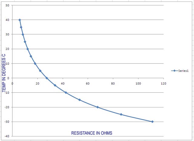
Plotting the data in Excel shows just how non linear the data is. Attempts to generate a polynomial equation to represent the data that was accurate within 1 degree failed, but by simple interpolation methods, we can very much get within that value by using the calibration table numbers in the range we are interested in. So this is what we indeed did.
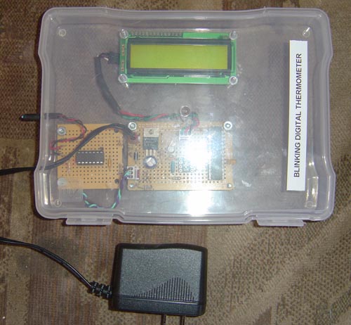
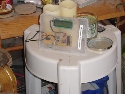
The finished unit looks like this, enclosed in a 10 inch wide polyethylene box with a nice hinged lid bought at a local craft store. The plug in 12v power supply is at bottom.
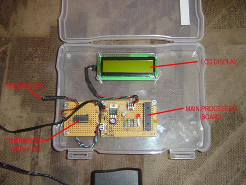
The case opened up to show more clearly the internal details. We used an old processor I had three of - a Microchip PIC16F876A with a nice 8k of program RAM and 10 bit analog inputs. They cost less than $2 these days.
Here is where the project currently sits in the living room, on a small table across the room from one of the security web cams. You can easily see in broad daylight the LED flashing the code for the temperature. The code is like this: half a second flashes spaced at one second for the first digit, repeats for the second digit, then a four second gap. Its really easy to read the temp by just watching the LED flash!
Heres the movie of it in action.
Click to enlarge
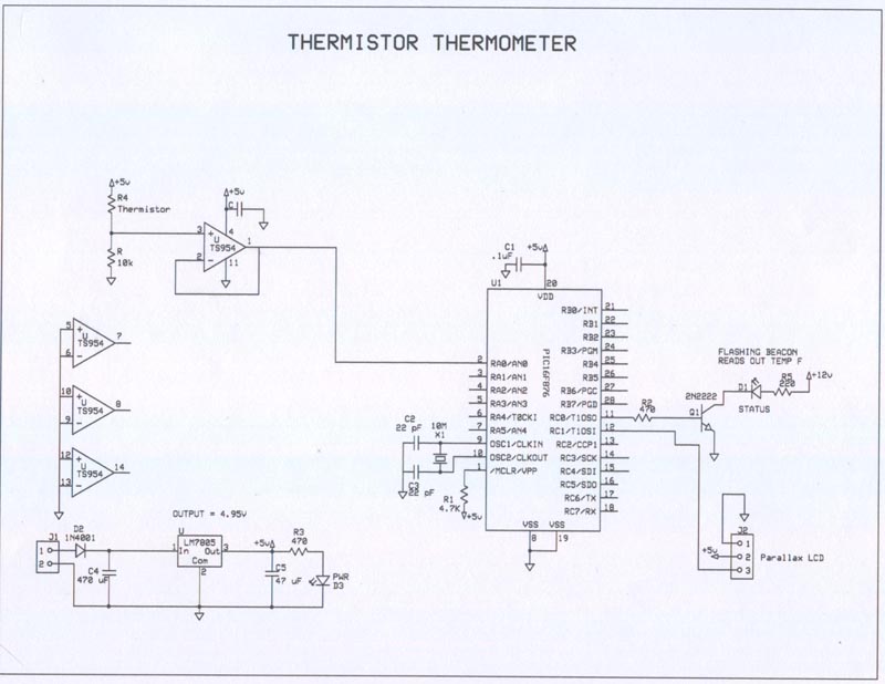
Schematic. I used a rail to rail quad op amp as a buffer for the thermistor divider output. This drives the 10 bit analog input for the micro, and we can then calculate the value of the thermistor by using a simple voltage divider equation since we very accurately have measured both the Vcc and series R values and stored that as a constant in the code.
Theory of operation:
Refer to the schematic above please. A standard 5 volt regulator provides power for both thermistor and the PIC micro. This allows me to set an absolute number to both the voltage dividers input and the analog reference (VDD) for the A/D converter. The PIC digitizes the values, calculates the actual resistance of the thermistor, then interpolates the table of values to get the actual temp in Centigrade. A final conversion to degrees F is done for LCD display. Finally after the reading is taken, the big red LED is flashed with a code to read out the value remotely.
Thermistor Math:
We start with the thermistor voltage divider. The thermistor resistance Rth is not known. But we do know the series R2 resistance accurately and the applied voltage Vdd. The output voltage Vo is measured and the we back calculate Rth:
Rth = (VinR2/Vo) - R2
So for example if we use 5v with a series R of 9.89K I measured an output of 2.182 volts, we get a true Rth of 12.77k ohms which is around 18.7C or 65F after interpolation.
Interpolation of table values:
The table is tabulated in 5 degrees C steps. To interpolate, we calculate the percentage above the lower value in the thermistors resistance range for that block of temps, and apply that to the actual 5 degree range to determine the offset up from the bottom.
So first determine the 5 degree block your in and calculate the deltas: Delta = (HiRtable - Rth)
Next the percent up from this bottom table value: Percent = (Delta/total range)
Offset from bottom in C = (5deg C * percent)
Final temp = (Lower C temp + offset)
So to make sense of these equations, lets take a typical example and work through it.
Taking the voltage divider reading above of 2.182 volts, we deduced the Rth had to be 12772.7 ohms (12.7k). From the thermistors resistance table, we can see this is in the range of 15 to 20C. The resistance values for this range is 14680 for 15C and 12100 for 20C. Delta = (14680 - 12772) = 1901 ohms.
Total range is 2590 for this block of 5 degrees, so Percent = (1901/2590) = .733 or 73.3% up from bottom of range.
Offset from bottom of range is therefore: C = (5 * .733) = 3.66 Degrees C.
Final temp is then: (15C + 3.66C) = 18.66C.
calculating the C to F is next: F = (C * 1.8) + 32 which in this case is (18.66 * 1.8) + 32 = 65.6F.
Flashing the Lamp with the Temp in F:
The temp in F is first converted to an integer and the decimal portion is stripped out. To isolate the first digit, we divide the temp by 10. The resulting integer is the first digit. To get the second digit isolated we multiply the first digit BY 10 and then subtract it from the original F reading. This gives the second digit by itself. Now it is a simple matter to encode the flashing light to represent the digits.
Sequence:
-- Flash for half a second spaced at 1 second the first digit. (ie: 7 is 7 flashes)
-- space between is 1 second
-- Flash for half a second spaced at 1 second the second digit. (ie: 4 is 4 flashes, 0 would be no flashes)
-- 4 second gap
-- Repeat.
The long flash times were chosen such that the indoor exposure of the web cam which varied from 1/4 to 1/2 second during the day would not truncate the flashes! You can obviously adjust this to suit your security camera.
Code Description:
All code was written with CCS-C and the PIC was burned with their Mach X chip burner. - Define all inputs/outputs - Define setups and constants used in equations - Main program - setup inputs and ADC -Read ADC, calculate Rth - Assign case to appropriate resistance range, and calculate all interpolation values - convert C to F - Flash LED with temp C Code: //**************************************************************************** //Chris Schur //Date: 3/26/16 //**************************************************************************** /*Description of this Program: This Program takes readings from a thermistor and converts to LCD output and flashes LED the temp in F //I/O Designations --------------------------------------------------- // RA0: - Analog Input: Sensor voltage in (0 - 5v) // RA1: // RA2: // RA3: // RA4: (Open Collector output) // RA5: // RB0: // RB1: // RB2: // RB3: // RB4: // RB5: // RB6: // RB7: // RC0: Status LED output // RC1: Digital Output: LCD out // RC2: // RC3: // RC4: // RC5: // RC6: // RC7: //-------------------------------------------------------------------- //Include Files: #include <16F876A.h> //Normally chip, math, etc. used is here. //Directives and Defines: #device ADC=10 //Set ADC when used to 10 bit = 0 - 1023 #fuses NOPROTECT,HS,NOWDT //xtal is used #use delay(crystal=10MHz) //xtal speed #use fast_io(ALL) //must define tris below in main when using this #define VOLTAGE 5.040 //Regulator Voltage #define R2 9890 //Series Resistance Ohms //For serial Parallax LCD only: #use rs232(baud = 9600, xmit=Pin_C1, bits=8, parity=N, INVERT, stream = LCD) //NO_ANALOGS is default in device file... //Interrupts: //**************************************************************************** //Global Variables: int16 RESULT; //a/d conversion of sensor float Rth; //Thermistor Resistance float Vo; //Calculated output of A/D in volts float VperBit; //Volts Per bit from A/D int8 range; //temp range in table 1-8 float delta; //difference between low end of range and Rth float percent; //decimal percent up from bottom of range float offset; //temp in C up from bottom of range float temp; // temp in C float tempF; //temp in F int8 tempFint; //temp in F integer part only int8 n,m; //temp digits separately int8 i; //counting variable //**************************************************************************** //Functions/Subroutines, Prototypes: void rangecalc(void); void Fcalc(void); void flash(void); //**************************************************************************** //-- Main Program //**************************************************************************** void main(void) { // Set TRIS I/O directions, define analog inputs, compartors: set_tris_A(0b11111); set_tris_B(0b11111111); set_tris_C(0b11111100); setup_adc_ports(AN0); //sensor v input is 0 - 5v setup_adc(ADC_CLOCK_DIV_32); set_adc_channel(0); //(analog inputs digital by default) //Initialize variables and Outputs: -------------------------------------- output_low(Pin_C0); //status off RESULT = 0; delay_ms(750); //Let LCD warmup. //Setup for timers, PWM, and other peripherals: //---------------------------------------------------------------- //MAIN LOOP: while (true) { //take reading on analog 0 input: result = read_adc(); //Next calculate the value of the thermistor currently. first calculate the //voltage that the A/D is reading: // 0 to 1024 max = 0v to VOLTAGE // Volts/bit = VOLTAGE / 1024 = VperBit VperBit = VOLTAGE / 1024; // Current value from A/D: // Vo = RESULT * VperBit Vo = RESULT * VperBit; //Current value for thermistor: //Rth = (Vin * R2)/Vo Rth = ((VOLTAGE * R2) / Vo) - R2; //Set up ranges for temp calculations. this is from cal sheet with part: rangecalc(); //Next we take the value in its approprite range and interpolate temp in C. switch (range) { case 1: delta=(111300-Rth); //-30 - 25c delta R = 24900 ohms for 5 degr. percent=(delta/24900); //fraction up from bottom of range offset=(5 * percent); //degrees offset up from bottom temp = -25 + offset; break; case 2: delta=(86390-Rth); //-25 - 20c delta R = 18700 ohms for 5 degr. percent=(delta/18700); //fraction up from bottom of range offset=(5 * percent); //degrees offset up from bottom temp = -25 + offset; break; case 3: delta=(67740-Rth); //-20 - 15c delta R = 14300 ohms for 5 degr. percent=(delta/14300); //fraction up from bottom of range offset=(5 * percent); //degrees offset up from bottom temp = -20 + offset; break; case 4: delta=(53390-Rth); //-15 - 10c delta R = 10900 ohms for 5 degr. percent=(delta/10900); //fraction up from bottom of range offset=(5 * percent); //degrees offset up from bottom temp = -15 + offset; break; case 5: delta=(42450-Rth); //-10 - 5c delta R = 8600 ohms for 5 degr. percent=(delta/8600); //fraction up from bottom of range offset=(5 * percent); //degrees offset up from bottom temp = -10 + offset; break; case 6: delta=(33890-Rth); //-5 - 0c delta R = 6600 ohms for 5 degr. percent=(delta/6600); //fraction up from bottom of range offset=(5 * percent); //degrees offset up from bottom temp = -5 + offset; break; //------------------ 0 degrees C line ------------------------------ case 7: delta=(27280-Rth); //0 - 5c delta R = 5300 ohms for 5 degr. percent=(delta/5300); //fraction up from bottom of range offset=(5 * percent); //degrees offset up from bottom temp = offset + 0; break; case 8: delta=(22050-Rth); //5 - 10c delta R = 4000 ohms for 5 degr. percent=(delta/4000); //fraction up from bottom of range offset=(5 * percent); //degrees offset up from bottom temp = offset + 5; break; case 9: delta=(17960-Rth); //10 - 15c delta R = 3300 ohms for 5 degr. percent=(delta/3300); //fraction up from bottom of range offset=(5 * percent); //degrees offset up from bottom temp = offset + 10; break; case 10: delta=(14680-Rth); //15 - 20c delta R = 2600 ohms for 5 degr. percent=(delta/2590); //fraction up from bottom of range offset=(5 * percent); //degrees offset up from bottom temp = offset + 15; break; case 11: delta=(12090-Rth); //20 - 25c delta R = 2100 ohms for 5 degr. percent=(delta/2090); //fraction up from bottom of range offset=(5 * percent); //degrees offset up from bottom temp = offset + 20; break; case 12: delta=(10000-Rth); //25 - 30c delta R = 1690 ohms for 5 degr. percent=(delta/1687); //fraction up from bottom of range offset=(5 * percent); //degrees offset up from bottom temp = offset + 25; break; case 13: delta=(8313-Rth); //30 - 35c delta R = 1370 ohms for 5 degr. percent=(delta/1372); //fraction up from bottom of range offset=(5 * percent); //degrees offset up from bottom temp = offset + 30; break; case 14: delta=(6941-Rth); //35 - 40c delta R = 1120 ohms for 5 degr. percent=(delta/1120); //fraction up from bottom of range offset=(5 * percent); //degrees offset up from bottom temp = offset + 35; break; case 15: delta=(5826-Rth); //40 - 45c delta R = 910 ohms for 5 degr. percent=(delta/910); //fraction up from bottom of range offset=(5 * percent); //degrees offset up from bottom temp = offset + 40; break; } Fcalc(); //calculate F value from C //Calbibration offset. makes it agree with the other digi thermometers. tempF = tempF - .5; //next send to the top line of the display: fputc(254,LCD); //Non Text INSTRUCTION BYTE TO FOLLOW delay_ms(1); fputc(1,LCD); //CLEAR SCREEN delay_ms(10); fprintf(LCD,"Temp= %3.1f",tempF); //temp in F //truncate decimal: tempFint = tempF; //integer temp, no decimal n = tempFint/10; //first digit of temp 0 - 13 m = tempFint - (n * 10); //second digit 0 - 9 //fputc(254,LCD); //Non Text INSTRUCTION BYTE TO FOLLOW //delay_ms(1); //fputc(192,LCD); //move to start of line 2 //delay_ms(10); // fprintf(LCD,"n= %u",n); //fprintf(LCD," m= %u",m); //fprintf(LCD,"Temp= %3.1f",temp); //temp in C if (tempF >= 0) //dont try to flash negative numbers flash(); delay_ms(4000); //display time -space between flash sets. } } //********* Functions which have prototypes at top of program **************** void rangecalc(void) { if ((Rth <= 111300) && (Rth > 86400)) //-30 to -25C range = 1; if ((Rth <= 86400) && (Rth > 67700)) //-25 to -20c range = 2; if ((Rth <= 67700) && (Rth > 53400)) //-20 to -15c range = 3; if ((Rth <= 53400) && (Rth > 42500)) //-15 to -10c range = 4; if ((Rth <= 42500) && (Rth > 33900)) //-10 to -5c range = 5; if ((Rth <= 33900) && (Rth > 27300)) //-5 to 0c range = 6; if ((Rth <= 27300) && (Rth > 22000)) //0 to 5c range = 7; if ((Rth <= 22000) && (Rth > 18000)) //5 to 10c range = 8; if ((Rth <= 18000) && (Rth > 14700)) //10 to 15c range = 9; if ((Rth <= 14700) && (Rth > 12100)) //15 to 20c range = 10; if ((Rth <= 12100) && (Rth > 10000)) //20 to 25c range = 11; if ((Rth <= 10000) && (Rth > 8310)) //25 to 30c range = 12; if ((Rth <= 8310) && (Rth > 6940)) //30 to 35c range = 13; if ((Rth <= 6940) && (Rth > 5820)) //35 to 40c range = 14; if ((Rth <= 5820) && (Rth > 4910)) //40 to 45c range = 15; } void Fcalc(void) { tempF = (temp * 1.8) + 32; } void flash(void) { //flashes the digit for the temp integer value for (i=1;i<=n;i=i+1) { //flashes digit for 0 - 13 times for 10 to 130F output_high(Pin_C0); delay_ms(500); output_low(Pin_C0); delay_ms(500); } delay_ms(2000); for (i=1;i<=m;i=i+1) { //flashes second digit for 0-9 times for 0 to 9F output_high(Pin_C0); delay_ms(500); output_low(Pin_C0); delay_ms(500); } return; } //flash