High Precision
Servo Driver Box
Uploaded: 1/14/15

This project will be used as a bench test component for setting up servos in other projects, including robots, and other moving devices. The knob is read with a 10 bit A/D and converted to a .5 to 2.5mS output pulse to drive a standard servo with an attachable digital display (used for other bench tests as well) for four digit accuracy in pulse width settings. This was my first major project written entirely in C. :o
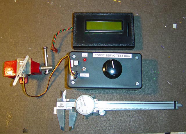
Below: Bench setup, with servo in small red vice, servo test box and illuminated LCD display.
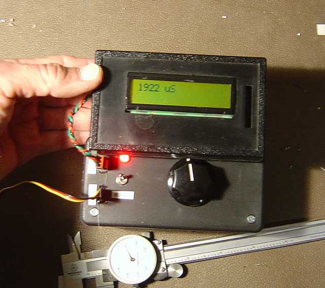
Below: Accurate 4 digit readings of pulse width. Essentially, 2mS range in 1024 steps. 9v batt
inside the box.
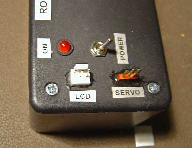
Below: Hookup connectors for Servo and LCD, a black foam block covers it when not in use.
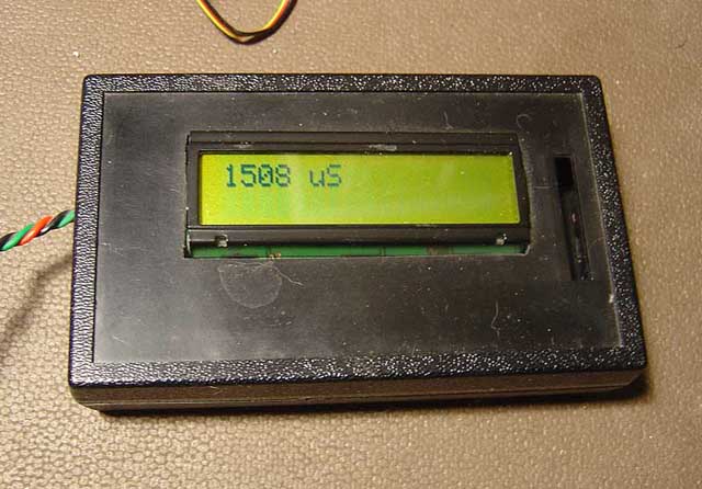
Below: 1.508mS shown as 1508uS
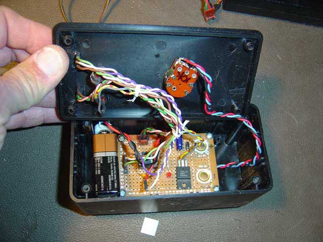
Below: Inside the box
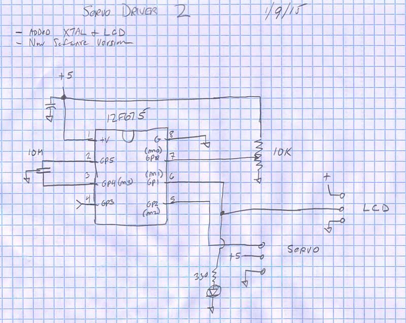
Below: Schematic of board - 12F675 processor. An xtal is used for running the processor at 10Mhz, so it can
operate the LCD.
Code:
//**************************************************************************** //Chris Schur //Servoboard Knob test box: 12F675 //Date: 1/4/15 //**************************************************************************** /*Description of this Program: This program Will take the push button controlled servo test board, add a pot and use that instead to vary the pulse output from .5ms to 2.5ms */ //I/O Designations --------------------------------------------------- // A0 (GPIO0): (An0) POT INPUT // A1 (GPIO1): (An1) LCD & LED OUT // A2 (GPIO2): (An2) SERVO PULSE OUTPUT -or- LCD OUT // A3 (GPIO3): X (can ONLY be input) // A4 (GPIO4): XTAL OUT (An3) // A5 (GPIO5): XTAL IN //-------------------------------------------------------------------- //Include Files: #include <12F675.h> //Normally chip, math, etc. used is here. //Directives and Defines: #device ADC=10 //This directive will only work if put RIGHT HERE first... #fuses NOPROTECT,NOMCLR #use delay(crystal=10MHz) #use fast_io(A) #use rs232(baud = 9600, xmit=Pin_A1, bits=8, parity=N, INVERT, stream = SERIAL) //**************************************************************************** //Global Variables: //******************************************/ //Functions/Subroutines, Prototypes: //**************************************************************************** //-- Main Program //**************************************************************************** void main(void) { // Set TRIS I/O directions, define analog inputs, compartors: set_tris_A(0b101001); //sets port directions //(analog inputs digital by default) setup_adc_ports(sAN0); setup_adc(ADC_CLOCK_DIV_32); set_adc_channel(0); //Initialize variables and Outputs: -------------------------------------- int16 result; //0 - 1023 out of ADC int16 on_pulse; //servo high pulse width in uS output_low(PIN_A1); //turn off status led //---------------------------------------------------------------- //MAIN LOOP: while (true) { //First read ADC result = read_adc(); //calculate pulse width: on_pulse = (2*result) +500; //for a range of .5mS to 2.5mS //next send pulse to servo output: output_high(PIN_A2); //servo out = 1 delay_us(on_pulse); //high time output_low(PIN_A2); //turn off pulse delay_ms(4); //space between pulses=20 with lcd serial delays fputc(12,SERIAL); //Clear screen delay_ms(1); fprintf(SERIAL,"%Lu"on_pulse); delay_ms(1); fputs(" uS",SERIAL); delay_ms(2); } } //********* Functions which have prototypes at top of program ****************