
Here is an amusing project, which my main purpose was to first - use up the last three PIC12F675 processors I had in my parts drawers, and second - to experiment with a tricolor RGB LED. The final project took about a week in spare time after work to produce, and produces a very brilliant, and very pure light for each color. So much fun in the dark at night!
Here are some images, schematic, and code in CCS-C for this interesting piece of hardware. I built it into a strong metal enclosure, and it runs nicely on two 9v batteries. The functional description follows in each panel.
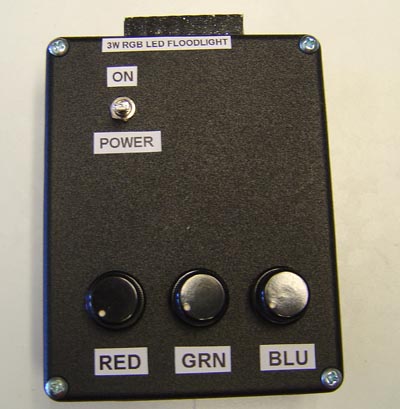
The box is a strong cast aluminum enclosure four inches wide, painted wrinkle black. (Allied Electronics) When the power switch is ON, the knobs adjust the individual brightness of each 1 watt color LED in the lamp, for a total of 3 watts when all are on. The range is off to full brightness with each knob. The little tab at the top? Thats so you cant see the side of the super bright LED and have it blast you with its side light. (You will see purple spots for a while)
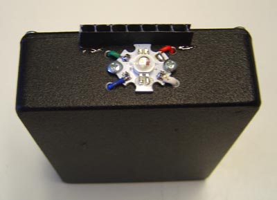
End on view of 3W LED. There are three chips in one bubble lens, and the output is a full 180 degrees producing a flood effect. By mounting the unit directly on the metal box, we heat sink the back and keep all cool since 3w is pretty hot in such a small package!
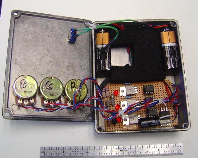
Inside the box. Two batteries at the top for power, and below is the circuit board with the 3 PIC's, a voltage regulator for them, three TIP120 power darlingtons (my favorites), some filter caps, and the power resistors. (2W). The black foam is to keep everything inside from rattling. On the left are the three 100k pots. I would have preferred 10k pots, but thats all I had in the junk drawer...
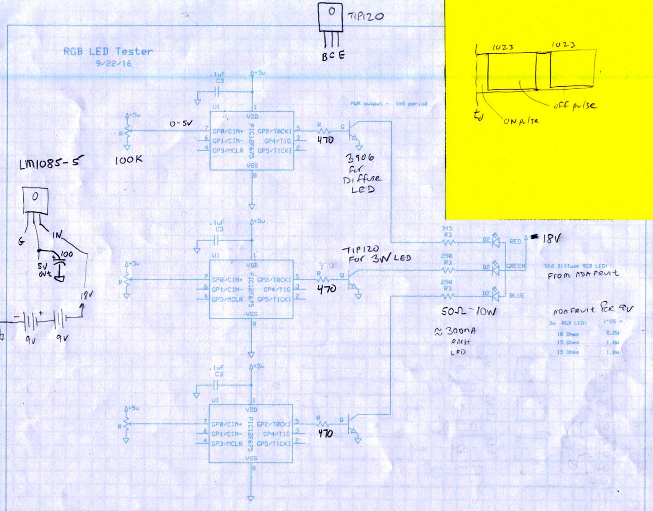
Schematic - CLICK TO ENLARGE.
Theory of Operation: The PIC's read the pot and digitize to 10 bit. Then put out a PWM signal at 1khz period that varies from about 10uS to full on in response. The TIP120s are a high gain power Darlington NPN transistor which drive the series R's to drive both the on board small red LED's and onward to the power resistors to drive the 3W RGB Led. The LED was obtained from Adafruit. (adafruit.com)
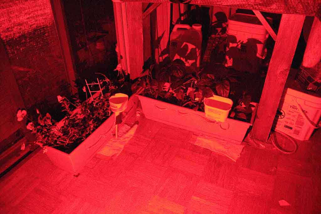
Here are some tests in the house at night to show the effects of separate and combined light colors on a planter we have near the kitchen. This is the very same plants our autonomous robot has been watering for nearly a year now, and are growing well. They are bell pepper plants. The entire room lights up when you turn those LED's on. I used a hand held camera to take these!
The first image is in RED light:
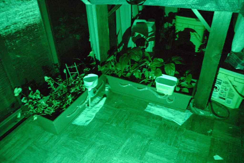
Next, we turn on only the GREEN light:
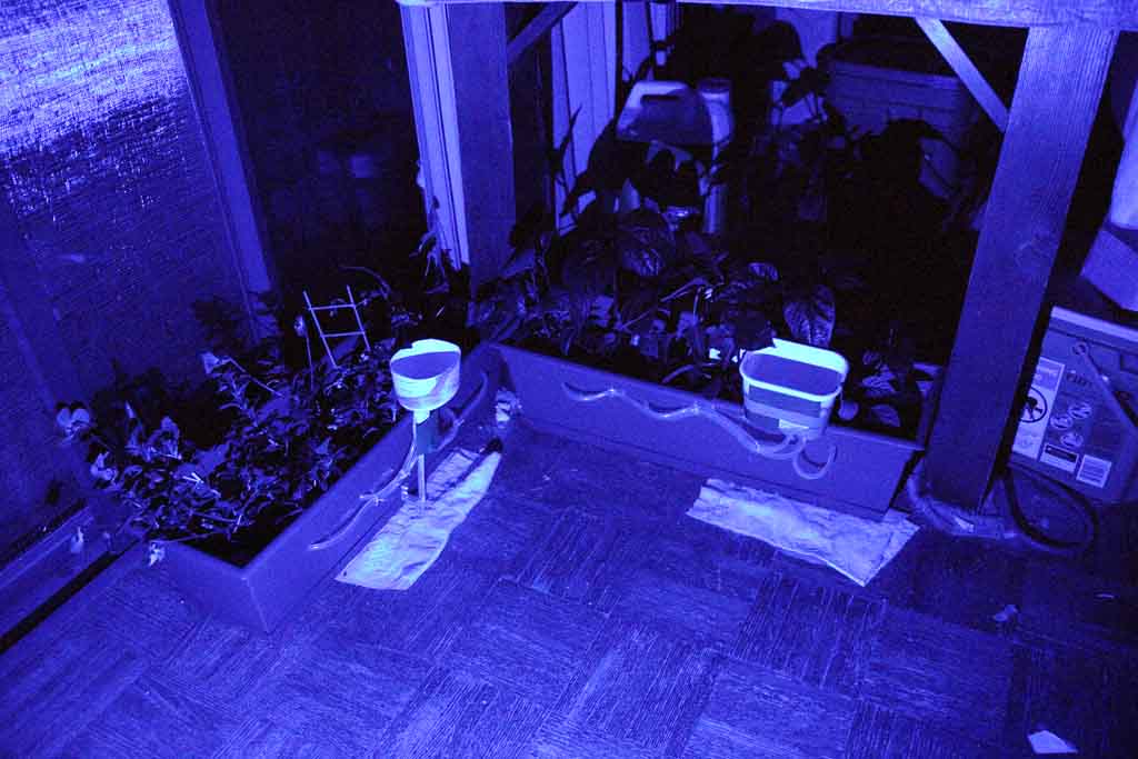
Finally we use only the BLUE light:
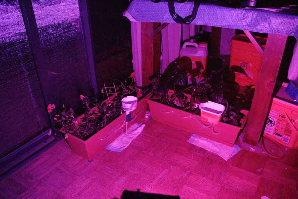
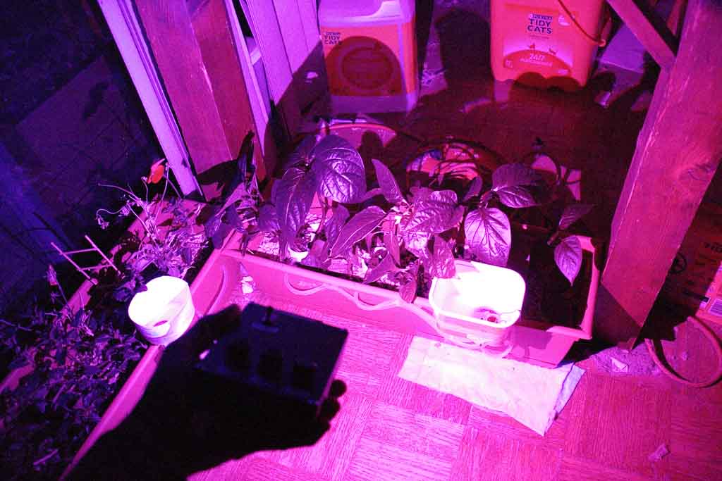
Now here is the color of a typical plant lamp - RED + BLUE (Wow, look at the color of those leaves!)
Looking closer, we can see the leaves are black. This is because all of the magenta light is absorbed. Pretty cool, ay?
Code for this project: CCS-C Compiler
//****************************************************************************
//Chris Schur
//Project Name here: 12F675 NO xtal LED PWM
//Date: 9/23/16
//****************************************************************************/*Description of this Program: This program Will use the 100k pot and vary the
PWM out put from near zero on time to near 100% on time at a pulse period of
1ms. Works great!*///I/O Designations ---------------------------------------------------
// A0 (GPIO0): An0 = Potentiometer Input
// A1 (GPIO1): X (An1)
// A2 (GPIO2): Digital Output to LED
// A3 (GPIO3): X (can ONLY be input)
// A4 (GPIO4): X (An3)
// A5 (GPIO5): X//--------------------------------------------------------------------
//Include Files:
#include <12F675.h> //Normally chip, math, etc. used is here.
//Directives and Defines:#device ADC=10 //This directive will only work if put RIGHT HERE first...
#fuses NOPROTECT,NOMCLR
#use delay(internal=4MHz)
#use fast_io(A)//****************************************************************************
//-- Main Program
//****************************************************************************void main(void) {
// Set TRIS I/O directions, define analog inputs, compartors:
set_tris_A(0b101001); //sets port directions
//(analog inputs digital by default)
setup_adc_ports(sAN0);
setup_adc(ADC_CLOCK_DIV_2);
set_adc_channel(0);
//Initialize variables and Outputs: --------------------------------------
int16 result; //0 - 1023 out of ADC
int16 on_pulse; //LED high pulse width in uS
int16 off_pulse;
//----------------------------------------------------------------//MAIN LOOP:
while (true) {
//First read ADC
result = read_adc(); //0 - 1023
//calculate pulse width:
on_pulse = (result); //for a range of 0 to 1023uS
off_pulse = (1023 - on_pulse);
//next send pulse to servo output:
if (on_pulse > 20) { //The fastest you can on off is like 20us. so we do this
output_high(PIN_A2); //LED out = 1
delay_us(on_pulse); //high time
output_low(PIN_A2); //turn off pulse
delay_us(off_pulse); //remainder of 1ms PWM pulse max
} //if
} //while} //main