

Here is our first data recorder project using a 12F1840 microcontroller. The unit is placed in a location either outdoors or indoors and activated. Then it records the temperature and brightness for 24 hours in non volatile EEPROM. After the recording is finished, the recorder is connected to a TTL/RS232 interface box which is then connected to the 232 port on a laptop. The data is then dumped into a terminal program, and the data then plotted in Excel.
Theory of operation.
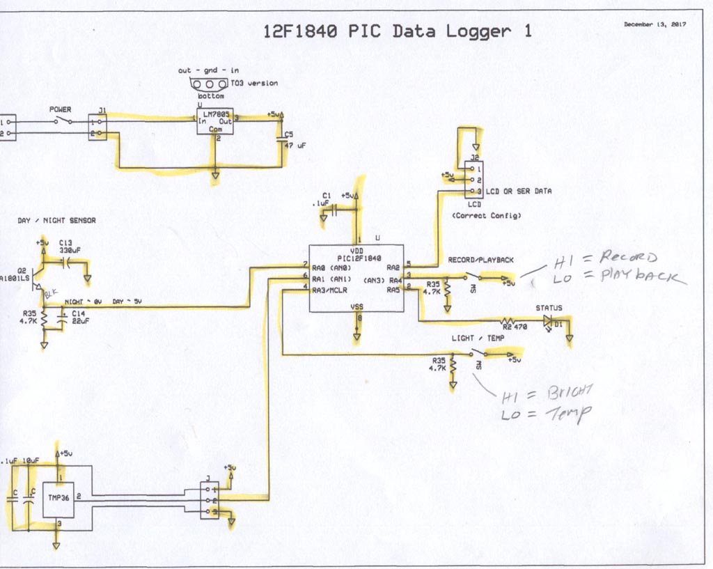
Here we are using the IR phototransistor to measure the brightness by generating a voltage from current through a 4.7k resistor. This is directed into one analog input on the microcontroller. For temperature, a TMP36 analog IC is used. This three terminal device puts out 10mv / C plus a 500mv offset. This allows it to measure both positive and negative values of Centigrade temperature. This is directed into a second analog input. Three switches are provided. One is power which turns on the 9v to the board. A small 5v regulator sets the voltage very accurately to around 4.95v. The micro uses this as its reference for analog measures. In record mode, set by a second slide switch, the processor starts recording the data in pairs. Every 15 minutes it takes one brightness and one temp reading and saves to EEPROM. A total of 100 sets is taken over a 24 hour period. When finished, it blinks the LED to let you know its done. Next, to read out, you turn on the second switch to "Playback" and power up. The processor dumps the temp or bright data according to the third switch. This separates the data into two streams for easy saving. The terminal program displays the data, which is then saved by copy and paste into notepad.
Design considerations.
Some photos of the device: (Click to enlarge to full size)
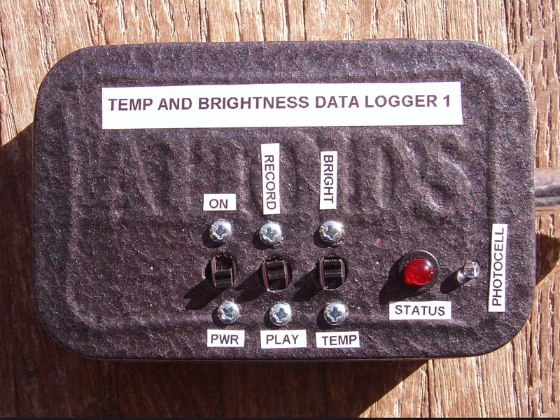
Outside of the housing, which is a painted "Altoids" Mint can. Ive been wanting to use one of these for a small project for years now. This is perfect! Three switches for setup are on the left, with the one LED status lamp on the right. The tiny T1 photocell is just to the right of the LED.
To read the external temperature, the sensor is in a vinyl tube extending from the box in and sealed on the end. This prevents any warmth from the inside of the metal box from affecting the temperature readings.
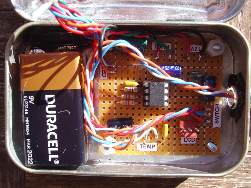
Inside the box, we see the 9v battery on the left, and circuit board on the right with the PIC12F1840 processor in the center. The unit draws from 7 - 9 ma nominally and the battery will last a very long time. A tiny LM7805 regulator is to the upper right in a small epoxy package.
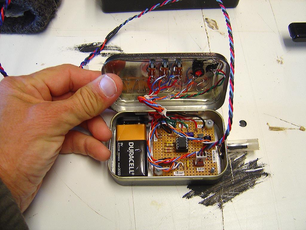
The wiring on the lid.
Schematic.
Downloading setup on the bench with a RS232 interface I built as an earlier project, and the laptop computer. Windows XP comes with a terminal program. Newer versions of Win you get nothing. :(
Hookup to download connects to a 3 pin Molex Waldom connector on the board.
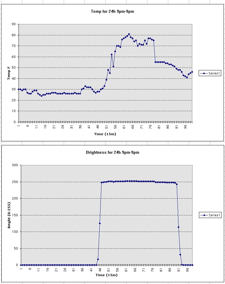
First outdoor test run. Several problems are encountered here. First, the box sat right in the sun, and heated up fast. This shows a run from 9pm the night before to 9pm the next day - 24 hours. The temp at night is around 26 degrees F, and the brightness graph on the bottom shows zero light. But after sun up the sensor which is black heated well beyond the outdoor temp of 47 degrees to over 80F, and the light detector was saturated by the bright sun full force.
The next run we are putting it in a diffuser housing to keep direct sun off the box.
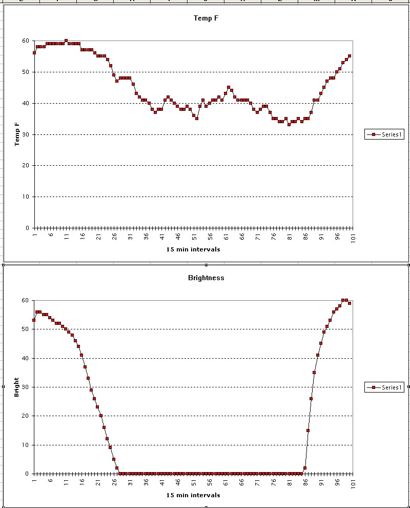
Final Test run. Here, we decreased the gain by 10x for the photocell and then put the recorder on the north side of the house to be out of the direct sun. This not only gave a nice brightness trace, but kept the sun from overheating the temp sensor. This is from noon to noon the next day.
C Code: (CCS C)
//****************************************************************************
//Chris Schur
//(Program Name): 12F1840
//Date: 12/31/17
//****************************************************************************/*Description. Data Logger, records and plays back RS232 to terminal
program data at 15 min intervals.
*/
//I/O Designations ---------------------------------------------------
// A0 (RA0): Input - Brightness sensor
// A1 (RA1): Input - Temp Sensor
// A2 (RA2): Output - Serial out put to LCD or computer
// A3 (RA3): Input - Brightness / Temp Switch (can ONLY be input)
// A4 (RA4): Input - Rec/Playback switch
// A5 (RA5): Output - LED//--------------------------------------------------------------------
//Include Files:
#include <12F1840.h> //Normally chip, math, etc. used is here.
#device ADC=10 //Set ADC when used to 10 bit = 0 - 1023//Directives and Defines:
#fuses NOPROTECT,NOMCLR //Makes port RA3 an input.
#use delay(internal=4000000)
#use fast_io(A)//For sending data out serial to computer:
#use rs232(baud=9600, xmit=Pin_A2, bits=8, parity=N,stream=TERMINAL)//Defines:
#define LED PIN_A5
//****************************************************************************
//Global Variables:
//****************************************************************************
int16 RESULT0; // AD0 conversion of sensor - 10 bit
float tf; //final temp in F
int8 tempf; //integer F for saving.
float volts; //calculated measured voltage mv in from sensor
int16 n; //counting var
float tc; //final temp in degrees c with decimal
int8 t = 0; //temp memory counter
int8 L = 1; //Light memory counterint16 brightR; //Raw brightness in 12 bits (0-1024)
int8 bright; //Raw brigtness scaled to 8 bit for saving.
int1 rwsw; //value of read/write switch
int1 tbsw; //value of temp/brightness switchint16 delayctr; //number of loops for 1 sec delay. 65535 = 18h between.
// for 100 sets = 1820h = 75 days...
//Functions/Subroutines, Prototypes:
void CALCTEMPC(); //Gets and Saves temp in C to tc.
void CALCF(); //calculate F from C set
void CONVERTF(); //converts F float to F 8 bit for storage.
void BRIGHTNESS(); //Measures and converts brightness to 8 bit for storage.
void READSW(); //Reads all switches and stores.
void FLASH3X(); //Flashes LED 3 times
void FLASH1X(); //Flashes LED 1 time
void FLASHFAST(); //Flashes LED 1 time fast
void ERASEEE(); //sets all data in memory to 0
void GETALLDATA(); //Gets temp and Light and fills EEPROM
void PLAYBACKBR(); //Playback Brightness
void PLAYBACKTF(); //Playback Temp F
//****************************************************************************
//-- Main Program
//****************************************************************************void main(void) {
// Set TRIS I/O directions, define analog inputs, compartors:
//(analog inputs digital by default)
set_tris_A(0b011011);
//Initialize variables and Outputs: --------------------------------------
output_low(LED);
delay_ms(2000); //LCD warmup time//Set all PortA to ANALOG:
SETUP_ADC_PORTS(sAN0 | sAN1,VSS_VDD);
SETUP_ADC(ADC_CLOCK_DIV_32);
RESULT0 = 0; //meas voltage raw 10 bit
delay_ms(2000); //lcd warmup
//----------------------------------------------------------------//MAIN Program:
READSW(); //Read in new Data or Write out stored data
if(rwsw) {
FLASH3X();
delay_ms(1000);
ERASEEE();
FLASH1X();//Next we record the data into eeprom for photocell and temp:
L = 1;
GETALLDATA(); //records all 200 bytes of data.while(true) //BLINK FOREVER AT END OF record
FLASH1X(); //Now turn power off and hook to computer for reading.
}//Otherwise read is selected. Now choose which to playback,temp or brightness:
output_high(Pin_A2); //set up serial - set back to hi so serial out starts right.
delay_ms(50);
t = 0;
L = 1; //reset EEPROM loc counterFLASH1X(); //ready to read out...
FLASH1X();
if(tbsw == 1) //brightness readout = 1, Temp = 0
PLAYBACKBR();//Otherwise read out temp:
PLAYBACKTF();
} //main
//********* Functions which have prototypes at top of program ****************
//Gets reading from temp sensor and calculates temp in C, saves to tc.
void CALCTEMPC() {
//take reading on analog 1 input:
set_adc_channel(1); //Select channel
delay_ms(10);
RESULT0 = read_adc(); //0 - 5v on input = 0 - 1024
//Next calculate the actual voltage in millivolts:
//for 5v ref, we use 4.88mv/bit. For 2v ref we use 1.953mv/bit
// 2.5v ref - 2.441
volts = 4.88 * (float)RESULT0;
//Next we convert to C:
tc = (volts - 500) / 10;
}void CALCF() { //calculates F from C
tf = (1.8 * tc) + 30; //adjust the 32 for cal factor!
}void CONVERTF() { //converts float F to int F for saving.
tempf = (int8)tf;
}void BRIGHTNESS() { //Measures and converts to 8 bit for saveing.
//Next we read photocell. night= 0v, Day= 5v.
//take reading on analog 1 input:
set_adc_channel(0); //Select channel
delay_ms(10);
brightR = read_adc(); //0 - 5v on input = 0 - 1024
bright = (int8)(brightR/4); //scales to 0 - 255 range
}void READSW() { //Reads switches and stores values
//here we read all switches and save results.
rwsw = input(Pin_A4); //read / write mode: 0=read, 1=write
tbsw = input(Pin_A3); //temp / brightness playback: 0=temp, 1=brightness
}
void FLASH3X() {
for(n=0;n<=3;n++) {
output_high(LED);
delay_ms(100);
output_low(LED);
delay_ms(100);}
}void FLASH1X() {
output_high(LED);
delay_ms(250);
output_low(LED);
delay_ms(250);
}void FLASHFAST() {
//flash FAST after every reading:
output_high(LED);
delay_ms(10);
output_low(LED);
delay_ms(10);
}void ERASEEE() {
//Erase EEPROM
for(n=0;n<=202;n++)
write_eeprom(0,n);
}void GETALLDATA() {
while(L<=203) { //temp is stored in evens, Light in odds. So start L=1,stop L=201
CALCTEMPC(); //get temp in C
CALCF(); //converts to floating F
CONVERTF(); //converts to int F for saving.
write_eeprom(t,tempf); //save int F in even location 0,2,4...
t = t + 2; //increment saving location t//next light data:
BRIGHTNESS(); //get 8 bit photocell data "bright"
write_eeprom(L,bright); //save int Bright in ODD location 1,3,5...
L = L + 2; //increment saving location LFLASHFAST();
//delay between readings. Table:
// Delaycounter: Delay: Total 100 sets time:
// 0 1 s 100s
// 35 36s 60mins
// 864 864s = 14.4m 24hdelayctr = 864; //set counter
for(n = 0; n <= delayctr; n++) //zero is counted as one loop.
delay_ms(952); //vary this number to get exactly 1 second for get loop. (952)}
}void PLAYBACKBR() { //Playback Brightness:
fprintf(TERMINAL,"\n\r"); //New line, Carrige Return
fprintf(TERMINAL,"Brightness Data:"); //text plus integer8 (Byte)
fprintf(TERMINAL,"\n\r"); //New line, Carrige Returnwhile(L<=199) {
bright = read_eeprom(L);
//send to TERMINAL:
fprintf(TERMINAL,"%u",bright);
fprintf(TERMINAL,"\n\r"); //New line, Carrige Return
delay_ms(25);
L = L + 2;}
while(true) //BLINK FOREVER AT END OF DUMP
FLASH1X();}
void PLAYBACKTF() {
fprintf(TERMINAL,"\n\r"); //New line, Carrige Return
fprintf(TERMINAL,"Temp F Data:"); //text plus integer8 (Byte)
fprintf(TERMINAL,"\n\r"); //New line, Carrige Return//Playback temp:
while(t<=198) {
tempf = read_eeprom(t);
//Send to TERMINAL:
fprintf(TERMINAL,"%u",tempf);
fprintf(TERMINAL,"\n\r"); //New line, Carrige Return
delay_ms(25);
t = t + 2;
}
while(true) //BLINK FOREVER AT END OF DUMP
FLASH1X();}