|
At our Observatory up
in Happy Jack (Clear Creek Canyon Observatory), my home built
mounting that carries my 8 inch Astrograph telescope was in need
of an upgrade to help locate those dim hard to find comets -
Setting Circles. The circles are used in conjunction with star
charts and computer maps to locate and center up moving targets
such as comets and asteroids.
This was a huge 3D printing
project! We made the Declination circle first as a proof of concept,
and the Right Ascension Circle second, and since it was too big
to print and had to be cut into four assemblies. Im happy to
report that the circles work fantastic, and set the telescope
directly on the position of many deep sky galaxies, nebula and
star clusters without any problems. Here is how they were made.
The Declination
Circle
Click on thumbnails
below for larger view:
 |
CAD
rendering in Solid works Visualize of the Declination circle,
complete with steel hardware and clamp. It is roughly 7 inches
in diameter and would just fit on the printer bed. |
 |
Solid
works CAD drawing of the circle before rendering. The degrees
are marked in 2.5 steps. Two clamps are provided. One squeezes
the DEC shaft for permanent setting. The second is a thumb screw
used in initial testing. |
 |
The
pointer for the DEC circle would be mounted on the declination
head on the mount and point to the circle angle. A slot is provided
on the pointing end for insertion of a red thin pointer made
of fiberglass circuit board material. |
 |
This
was going to be a major printing endeavor. We chose to print
it in glow in the dark PLA filament from Hatchbox. Here the circle
is taking shape! It took nearly 20 hours to do this print. |
 |
Turning
the lights off during printing at night, and the whole roll of
filament and the circle glows. |
 |
The
final print, in the dark. It will not glow this strongly when
on the telescope - this was charged up with a bright light just
before this shot. |
 |
In
the daytime you can see both the Declination Circle and its pointer.
The off-white color of the filament is very nice. |
 |
Edge
on view of the numbers on the edge. I blackened them with a fine
tip sharpie to increase contrast a bit, however that was not
really needed because you shine the flashlight on the circles
from the side to illuminate in the dark anyway. |
 |
Here Installed
on the mounting. The pointer is at the bottom here and the circle
slip turns on the Declination shaft. Once set, you never have
to set it again. It reads in degrees from the north pole in the
sky. (Polaris) |
 |
Side
view showing the pointer. I put a red strip of fiberglass in
the slot on the pointer to aid in setting accurately. |
The Right
Ascension Circle
 |
Next
we started designing the Right Ascension Circle. It is scribed
in 0 - 24 hours and had to be printed in four different interlocking
sections that had to be a perfect fit onto the gear on the mounting.
It slip turns to set. It all had to be smooth, accurate and not
bind or catch. They are a tongue and groove design to interlock.
Note that the 18h line is cut in half. The other half is on the
mating piece... |
 |
All
four sections together here in the CAD drawing proves the parts
fit and they are right in size. Would the printed parts fit this
well? |
 |
Solid
works Visualize rendering of the completed ring. |
 |
The
six studs will mount on the gear in threaded holes and retain
the gear in such a way as it can slip turn. This is one such
stud. Six 1/4-20 bolts retain these studs on the side of the
gear. By attaching the circle directly on the gear, the circle
is driven by the gear and once set will stay accurate all night
long. |
 |
The
pointer is two parts, first we have the actual pointer in which
we added a clear lexan pointer with a sharp tip to the right
side to overhang the circle to get the reading. |
 |
The
second part of the pointer is the attachment standoff for the
RA shaft. This hold the pointer over the circle and allows slip
turn over the shaft to set as well. |
 |
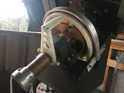
Finally,
the assembled ring (bolted together) is test fitted on the to
gear with the studs. It worked! Now to assemble the remainder
of the setup. The brass worm gear is just over 10 inches in diameter. |
 |
The
pointer system is installed. When you move the telescope in RA,
the pointer moves and indicates the Hour Angle on the scale. |
 |
Final
shot, the telescope on my home made mounting with the circles
attached ready for use. |
|


